Showing posts with label AutoCAD 2015. Show all posts

February 20, 2015

Notes from Afghanistan

Hey folks, I have not contributed to the ideate blog for quite some time as I have been deployed to Afghanistan for almost a year. Now that the war is over, and we are wrapping things up, preparing to come home, I finally have some time to write down some things I have been doing to keep my skillset up. As soldiers prepare to come home, mementos of time spent away from home begin to attract soldier’s attention.

In remembrance of our time spent here across the entire country of Afghanistan I decided to design a logo that I could give to all of my soldiers to remember their time and sacrifices spent here. Velcro Patches seem to be the in-thing amongst our soldiers so I decided to create a patch that represented our Battalion. To do this, I chose AutoCAD 2015 as my artwork in Photoshop is not that great, and I prefer to draw with straight lines and arcs as I have greater control.

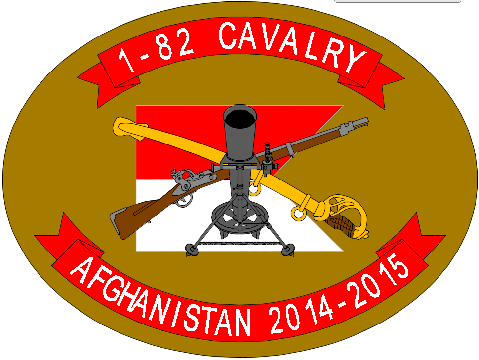
The unit I belong to is a Cavalry Squadron, and is comprised of Cavalry Scouts, Infantry Scouts, and Mortarmen, along with support assets. So these three things were crucial in the design. As I am a mortar platoon sergeant, of course the mortar took center stage. I drew a rifle representing the infantry branch and a saber to represent the cavalry branch all over a red and white cavalry guidon representing the 1-82 Cavalry Squadron. Ribbons with the squadrons name and the time spent in Afghanistan also adorn the design against a “coyote brown” background representing Afghanistan. It was very rewarding to actually get this in production. The tailor I used was very pleased with the crispness of the artwork and wanted to know what I used to create the artwork…AutoCAD 2015.

 I haven’t really dealt with AutoCAD for quite some time, but was impressed with the new hatching tools in the ribbon. My only frustration, as I am sure many of you have, is finding various tools amongst the ribbons. I found myself typing commands at the Command prompt as it seemed faster to do what I wanted rather than hunting around for the tool. One thing I wish AutoCAD did better was utilizing context sensitive menus like Revit. What I mean here is when accessing various tools, or editing various objects, I wish the ribbons would react to the thing that is being edited. As I used polylines to enhance the width of the various artwork, I was wishing for a ribbon to pop up with related toolsets for the polyline or polylines I had selected to edit. Regardless, AutoCAD is not dead. It still has its best use scenarios, and designing a logo for me was where AutoCAD helped me the most.

I have a few more blogs coming particularly in the Revit realm, where I have used Revit the past few months to help me keep a bit of home close and help pass the time. As we come down to our final days here, I want to thank you for your support as I have been away, thank you for the many veterans and their sacrifices you have gone through, and thank Bob Palioca and the crew at ideate for their support and understanding with me being absent. See you all soon…"Steel Rain”, out.
 
 
Visit Ideate Inc. on the web for more information on AutoCAD 2015 and more.


Ron Palma
Ideate AEC Application Specialist

Ron has over 24 years of experience in the architectural industry as a drafter, designer, lead project designer, trainer, and a CAD manager implementing Autodesk Architectural Solutions for a residential design firm. His instructional background includes being an Autodesk Certified Instructor, trainer, support technician, educator at Portland and Clackamas Community Colleges, as well as a U.S. Army certified instructor where he was a senior instructor at Ft Lewis Washington. Ron is a member of the Oregon Army National Guard and platoon sergeant, training and mentoring soldiers in their careers. Ron is a published writer and continues to author professional technical training manuals and shorts for AutoCAD, AutoCAD Architecture, and Revit. As an Autodesk Certified Instructor, Ron provides Revit Architecture training and support for AEC firms. Follow Ron @RonPalmaAEC.

Get it. Know it. Use it.

February 11, 2015

Removing Un-purgeable Linetypes using the Layer Translator for AutoCAD

I finally discovered a way to quickly remove line types that are seemingly un-purgeable.  This problem has come up many times while I’m on tech support here at Ideate Inc.  I found the solution buried in an Autodesk forum. This method uses the Layer Translator in an unconventional way. 

The Issue

You’ve inserted a drawing into your drawing.  After doing this, you realize the file is gigantic due to the extra line types and other objects that were inserted.  You then run purge multiple times, yet the line types are still there.


The Solution

1. Open the Layer Translator in the file that you are having an issue. The layer translator can be found on the manage tab.


2. Under the right hand box, choose the button "Load..." browse to the same file you have open (the file you are purging line types) This is the illogical part, but the Layer translator only brings with it the actual layers and settings that have been set in the manger. The extra line types not being attached to any specific layer are left out.


3. Once Layers have loaded select "Map Same" button in the middle of the two upper boxes.


4. Once the layers have been mapped they will show as having disappeared from the left hand box and all the layers will appear in the lower box. Select "Translate" button at the bottom.


5. On the next pop up select Translate Only.


6. After the translation is done, run the purge all command.

7. Run the audit

8. Purge all again.

9. Type in LT to pull up dialog and confirm that all excessive line types have been removed.


Kate Ming, P.E.
Ideate AEC Application Specialist

Kate is a California licensed civil engineer with a BS in Civil and Environmental Engineering from UC Berkeley. Prior to Ideate, she worked at a multinational company for four years doing general civil design on large infrastructure projects. She is versed in roadway, rail, utility design and site development. She also has experience with utility demand analysis and Low Impact Development plans. As a Civil 3D Autodesk Certified Professional Kate provides training and support for Civil 3D, AutoCAD, and InfraWorks.


February 4, 2015

AutoCAD 2015 Service Pack 2 Hotfix

There is a hotfix for Service Pack 2 for AutoCAD.  If you are having an issue with your AutoCAD freezing, closing abruptly, font or the layout tab, Service Pack 2 may be the problem.  I recently had a case while on tech support at Ideate where a customer’s AutoCAD software was closing abruptly.  We eventually escalated the case to Autodesk.   Autodesk informed us that there is a hotfix for Service Pack 2.

When SP2 (Service Pack 2) was first released, Autodesk found that 2 .DLL files in AutoCAD had been changed by the Service Pack, causing them to malfunction. In some computers, this caused several different issues, from text warping to the program hanging, and even layout tabs moving around of their own volition.

Below are links to the websites where you can download the new versions of the malfunctioning .DLL files.


There are instructions in the readme files, but essentially it involves renaming the two old files to .BAK, then downloading and unzipping the new files and dropping them into the C:\Program Files\Autodesk\AutoCAD 2015 directory, then restarting AutoCAD.

Replacing the two .DLL files should restore your system to normal operation.


Autodesk / AutoCAD Hotfix 1

Autodesk / AutoCAD Hotfix 2

Visit us for additional information on upcoming Ideate training and events!


Kate Ming, P.E.
Ideate AEC Application Specialist

Kate is a California licensed civil engineer with a BS in Civil and Environmental Engineering from UC Berkeley. Prior to Ideate, she worked at a multinational company for four years doing general civil design on large infrastructure projects. She is versed in roadway, rail, utility design and site development. She also has experience with utility demand analysis and Low Impact Development plans. As a Civil 3D Autodesk Certified Professional Kate provides training and support for Civil 3D, AutoCAD, and InfraWorks.


September 16, 2014

Lines Display Blurry or Unsharp in AutoCAD 2015

While working on Ideate Tech support, a client had an issue with lines showing up blurry in AutoCAD 2015. This turns out to be a known issue that Autodesk is looking into. There are some work-arounds, however. 

The solution

It is most likely related to your graphics card driver.  Below is a list of possible fixes:

Option 1

  1. Turn Smooth line display off in the Graphics Performance Box
Option 2
  1. Edit special settings of the NVidia driver, “NVidia FXAA Anti-Aliasing” = OFF. You can find the NVidia control panel by right clicking anywhere on your desk top and choosing the NVidia Control panel.  Once in there, go to the Manage 3D settings, and choose AutoCAD on the Program Settings tab.  From there, you can make sure Antialiasing – FXAA is turned off.  Refer to the image below. 
  2. Turn Hardware Acceleration on in AutoCAD
Option 3
  1. Uninstall AutoCAD 2015 
  2. Update your Graphics card Driver
  3. Re-install AutoCAD 2015
Here is a link to the documented solution from Autodesk.

For more information on Autodesk products, continue to check out our blog.  Additionally, visit our website for information on training and consulting for the various products Ideate services, visit our website at www.ideateinc.com.


Kate Ming, P.E.
Ideate AEC Application Specialist


Kate is a California licensed civil engineer with a BS in Civil and Environmental Engineering from UC Berkeley. Prior to Ideate, she worked at a multinational company for four years doing general civil design on large infrastructure projects. She is versed in roadway, rail, utility design and site development. She also has experience with utility demand analysis and Low Impact Development plans. As a Civil 3D Autodesk Certified Professional Kate provides training and support for Civil 3D, AutoCAD, and InfraWorks.


May 5, 2014

What’s New in Civil 3D 2015: Maintain Targets Even After Replacing Subassembly

In keeping you informed with ‘What’s New in my software’ series from Ideate; here is a snippet on one of the key benefits of Civil 3D 2015.

If you have always modeled corridors in Civil 3D and you have been dreading to change the subassembly because of the fear of losing targets. Read on… there is now a solution.

Enter Civil 3D 2015 – problem solved.

In Civil 3D 2015 you can now change a subassembly and yet maintain the corridor targets. In fact, when you add a subassembly from Tool Palette you are now prompted to insert, replace, or leave it detached at the command line.
 

New Command Line Options for Subassembly Insertion
If you chose to replace it then it will prompt you to maintain targets or not.

Similar Targets in Previous Subassembly Dialog Box

In this example I accidently choose the wrong subassembly for my left knuckle, as evidently seen below in the red highlight. Yes, I have exaggerated a bit.

Corridor With Old Subassembly in Assembly, Plan and Section View
I was able to replace it with minimal effort. All the while maintaining the left EOP knuckle target. Here is the screen shot after replacing the subassembly.
 
Corridor With New Subassembly

For these improvements and more, try out Civil 3D 2015 now. Also, remember to come back here to the Ideate Solutions blog for more details on the enhancements to Civil 3D 2015 from me and my team.

Check out the video Civil 3D 2015: Maintain Targets Even After Replacing Subassembly

Also, for information on training and consulting for the various products Ideate services, visit our website at www.ideateinc.com

Don’t forget to look through other great features our Ideate Technical Team has found in the new 2015 releases for Civil 3D, Navisworks, Revit Architecture, AutoCAD and more: ideateinc.com/2015


Gaurav Bagga
Ideate Infrastructure Solutions Application Specialist

Gaurav is a well rounded Application Engineer and Project Manager for Infrastructure Solutions at Ideate based out of San Francisco. He has over 15 years experience in construction industry and has been helping numerous small, medium and ENR 500 firms maximize their CAD investment for the last ten years. Gaurav is an Autodesk Certified Instructor and Autodesk Civil 3D Implementation Certified Expert. He has taught at several conferences, CAD Camps and Autodesk University. He has taught AutoCAD, Civil 3D, Land Desktop and Map 3D to thousands of students and helps Ideate develop the Infrastructure Services curriculum and courses. With his extensive CAD technology background he helps Bay Area engineering and surveying firms analyze and improve their design and drawing production process thereby improving productivity and the bottom line. Follow Gaurav on Twitter: @BeGeez

Get it. Know it. Use it.

April 30, 2014

Productivity Enhancements Using AutoCAD 2015 Reality Capture

Following up with the Ideate tradition of What’s New; here is another update for you in my software series.

AutoCAD 2015 brings new productivity enhancements for reality capture. Point Cloud workflow has been streamlined and simplified. You can simply open Autodesk ReCap from within AutoCAD to process LAS files and other proprietary point cloud data formats. You can now process that data and export a ReCap Scan RCS file from ReCap to XRef in AutoCAD. However, you will not be able to attach your existing PCG or ISD files any more. If you do have a project that was using these files you will still be able to modify the point cloud properties in AutoCAD 2015 in properties palette – don’t expect to see the contextual ribbon tab for this.

Once the point cloud is attached within AutoCAD it maintains its visual fidelity displaying scan colors. Here you see the same point cloud displayed in scan colors in AutoCAD 2015 to your left and AutoCAD 2014 to the right.
 
Left: AutoCAD 2015 Screen Capture      Right: AutoCAD 2014 Screen Capture


Furthermore, the visualization of point clouds has been enhanced in AutoCAD 2015. There is a new color mapping button that gives you the freedom to add a color palette of your choice to visualize your point cloud data. You can now colorize your point cloud data using elevation and classification. A new point cloud lighting tool has been added to help you visualize and present point cloud data professionally. Here is a snapshot of the point cloud tools in contextual ribbon tab.


In addition to visualization, there are performance enhancements – AutoCAD 2015 is able to handle point cloud data better and faster than AutoCAD 2014.

And I will leave you with this – you can now snap to plane on a point cloud to, let’s say, place a window on the point cloud wall. Stay tuned for more on this from Ideate’s blog and YouTube channel.
 

Check out the video AutoCAD 2015 Reality Capture Productivity Enhancements

Also, for information on training and consulting for the various products Ideate services, visit our website at www.ideateinc.com

Don’t forget to look through other great features our Ideate Technical Team has found in the new 2015 releases for Civil 3D, Navisworks, Revit Architecture, AutoCAD and more: ideateinc.com/2015


Gaurav Bagga
Ideate Infrastructure Solutions Application Specialist

Gaurav is a well rounded Application Engineer and Project Manager for Infrastructure Solutions at Ideate based out of San Francisco. He has over 15 years experience in construction industry and has been helping numerous small, medium and ENR 500 firms maximize their CAD investment for the last ten years. Gaurav is an Autodesk Certified Instructor and Autodesk Civil 3D Implementation Certified Expert. He has taught at several conferences, CAD Camps and Autodesk University. He has taught AutoCAD, Civil 3D, Land Desktop and Map 3D to thousands of students and helps Ideate develop the Infrastructure Services curriculum and courses. With his extensive CAD technology background he helps Bay Area engineering and surveying firms analyze and improve their design and drawing production process thereby improving productivity and the bottom line. Follow Gaurav on Twitter: @BeGeez

Get it. Know it. Use it.

April 24, 2014

AutoCAD 2015: Command and Selection Enhancements

Ideate is highlighting updates and enhancements made to Autodesk Software in the 2015 release. In this post, I will illuminate a few of the command and selection enhancements made in AutoCAD 2015.

Selection Enhancements
To me, one the most exciting new features is the lasso selection. To use the lasso selection left click in the drawing to start the selection command, continue to hold down the left mouse button, and move around the objects that you would like to select. You can turn this function on and off on the selection tab of the options box. 

Example of lasso command.

Image: Where you turn the lasso selection on or off in the options dialog box.
Another addition to the selections is the glowing effect that selected objects have when hardware acceleration is on. This is so you can easily see what is selected. To turn on hardware acceleration on or off, type GRAPHICSCONFIG in the command line.

Image: Selected objects now glow when hardware acceleration is turned on.

Image: Selected objects remain dashed when hardware acceleration is turned off.
Command Enhancements
Many commands already have a command preview, such as the offset command. In AutoCAD 2015, many more commands have the command preview, such as trim, extend, match properties, and break. For example, the extend command will now give a preview of what the object will look like before you extend it by just hovering. Additionally, command preview is now an option that you can turn on or off. You do this in the options box.


Image: Command Preview option in options dialog box
Another command enhancement is the cursor badges. A cursor badge is a small icon that shows up along-side the cross hair. These badges show up while you are in a command. The images below show some of these badges.


Image: Command badges at the cross hair
Check out the video AutoCAD 2015: Command and Selection Enhancements

Also, for information on training and consulting for the various products Ideate services, visit our website at www.ideateinc.com

Don’t forget to look through other great features our Ideate Technical Team has found in the new 2015 releases for Revit MEP, Revit Structure, Revit Architecture, AutoCAD and more: ideateinc.com/2015


Kate Ming, P.E.
Ideate AEC Application Specialist

Kate is an Application Specialist at Ideate, Inc. and is a Professional Engineer with 6 years of industry experience. At Ideate, Kate provides training, consulting and technical support services for our customers.

Get it. Know it. Use it.

April 21, 2014

AutoCAD 2015: User Interface Updates

With 2015 Autodesk products now available AutoCAD users are starting to download and install the latest version to get a peek at what’s new in the latest and greatest release. Here are some of the more noticeable changes that Autodesk has made to overall appearance of AutoCAD 2015.

New Start Screen

Instead of the Welcome Screen that we’ve all gotten used to over the past few years, AutoCAD 2015 now has a new Start Screen that opens when the application is launched. The new Start Screen looks like a blank drawing tab, and is divided into two sections.


Create Page
The Create page is set up for all things drawing related. From the Create page, you can start a new drawing, select from a list of template files
(DWT) to create drawings, open existing drawings, sign-in to your Autodesk 360 account, and see Program Notifications for updates and performance related information.


Learn Page
The Learn page contains links and videos to references and resources related to AutoCAD 2015. Here you can find videos on Getting Started with AutoCAD, New Features, Tips, and Online Resources.


Switching from page to page is as easy as clicking on the links at the bottom of the screen.


New Dark Themed Ribbon and Customizable Status Bar
The Ribbon in AutoCAD 2015 has been updated to support a dark gray theme. In past releases, the Ribbon was a consistent lighter color regardless of the dark or light theme selected. The new darker theme provides a more consistent appearance when used with a dark Model Space background color.


The old format Status bar with icons lined along the bottom of the drawing area has also been updated in the 2015 release. We now have control over which status options are displayed at the bottom of the screen via the customize pop up list in the bottom right corner. The list includes all status options from Coordinate display to Clean Screen options. This pop up does not control the on/off functionality of the particular feature; just the display of the icon.


Check marks indicate which icons will appear on the Status bar for easy one-click on/off control. Common hotkey shortcuts also work, regardless of the icon being visible or not. This can make it somewhat confusing, so it is a good idea to keep the icons you intend to use visible on the status bar. Unfortunately, the option of displaying Text versions of the Status Icons is no longer available in 2015 through the right-click “Use Icons” option that was there in the past.  


The standard blue/gray color scheme still indicates the on/off status of the icons, and they are displayed based on which items you check in the customization pop up.

So what do you think about the new dark theme and customizable status bar? 

When you’re getting started with AutoCAD 2015, spend some time digging through the new user interface and see what other cool updates you can find. 
 

Check out the video: AutoCAD 2015: User Interface Updates

Also, for information on training and consulting for the various products Ideate services, visit our website at www.ideateinc.com

Don’t forget to look through other great features our Ideate Technical Team has found in the new 2015 releases for AutoCAD, Navisworks, Civil 3D, Revit Architecture, and more: ideateinc.com/2015


Matt Miyamoto, P.E.
Ideate AEC Application Specialist

Matt is a licensed Civil Engineer in the state of Hawaii. Matt obtained a BS in Mechanical Engineering from the University of Hawaii at Manoa, and has 7 years of private sector design experience which he applies in his role as an application specialist with Ideate, Inc. His project experience includes residential and commercial site development, private and public sewer, water and drainage systems, harbors improvements, and roadway improvements. While in Hawaii, Matt was involved in multidisciplinary projects for City and County agencies, State Departments, the Army COE and private developers. @MattM_PE

Get it. Know it. Use it.

March 27, 2014

Inserting a Bing Map Image - AutoCAD 2015

At Ideate we have been hard at work, rummaging through all of the new software and highlighting the most important new features in the 2015 product line. Last year AutoCAD added a function that allowed you to add map images from Bing to your drawings. This year, that functionality has been enhanced and improved.

Geolocation Map Insert Basics


First, I’d like to review how this function works. On the insert tab of your ribbon, you can access the Set Location > From Map function.  


After you agree to the terms of service, the Geographic Location – Specify Location (Page 1 of 2) box will pop up. Choosing a location is now broken into two pages within the Geographic Location box, as seen below. First, indicate an address in the Specify Location box. After you search and drop a pin at the location, click the next button go to the Set Coordinate System box. In here, only relevant coordinate systems are shown. Also, added to the 2015 release is the ability to search for other coordinate systems.


Once a coordinate system is selected and the center point and north arrow is specified, you will be allowed to zoom in and out on your image.


New Features


In addtion to the location tools and image type options (Map Aerial, Roads, Hybrid, or off) on the Geographic Location tab, you can Capture an Area and Viewport for plotting purposes and to preserve the current map data. This embeds the map into the drawing and allows you to work offline. 


After creating your Captured Area or Viewport, a Map Image tab will appear when the boundary of the area or viewport is selected. This tab has additional editing features, including changing the image resolution, brightness, contrast and fade. Additionally the boundary area can be edited using grips or other AutoCAD commands. Lastly, to ensure that the image is up to date, you can update the image while you are online.


To recap the new additions to the Image Map function, below is a list of the improvements.

  1. The Geographic Location box is now broken into two boxes, the first being the location and the second being the coordinate system 
  2. The ability to search for a coordinate system
  3. The ability to capture and embed an area with a selection box or viewport to be accessed when offline
  4. The Map Image tab that has Image Resolution, Image Controls, and Reload Image options for the embedded area
  5. The ability to edit the embedded map area grip and boundary using common commands
Keep up with the new and improved features of Autodesk software by regularly checking this blog. Ideate’s technical team is dedicated to sifting through and illuminating new and improved features in the 2015 releases. Also check out this video to learn more about Geolocation Map Insert Basics.

Also, for information on training and consulting for the various products Ideate services, visit our website at www.ideateinc.com


Don’t forget to look through other great features our Ideate Technical Team has found in the new 2015 releases for Revit MEP, Revit Structure, Revit Architecture, AutoCAD and more: ideateinc.com/2015


Kate Ming, P.E.
Ideate AEC Application Specialist

Kate is an Application Specialist at Ideate, Inc. and is a Professional Engineer with 6 years of industry experience. At Ideate, Kate provides training, consulting and technical support services for our customers.