December 30, 2014

A B C D Elevation Marks

Ever wanted to assign the letters A B C D on every interior elevation tag?  Find a way to cheat the Revit interior elevation pointer behavior and display in sheets the interior elevations the way you want.

Add text to the interior elevation mark to achieve a consistent view designation letter for every orientation.
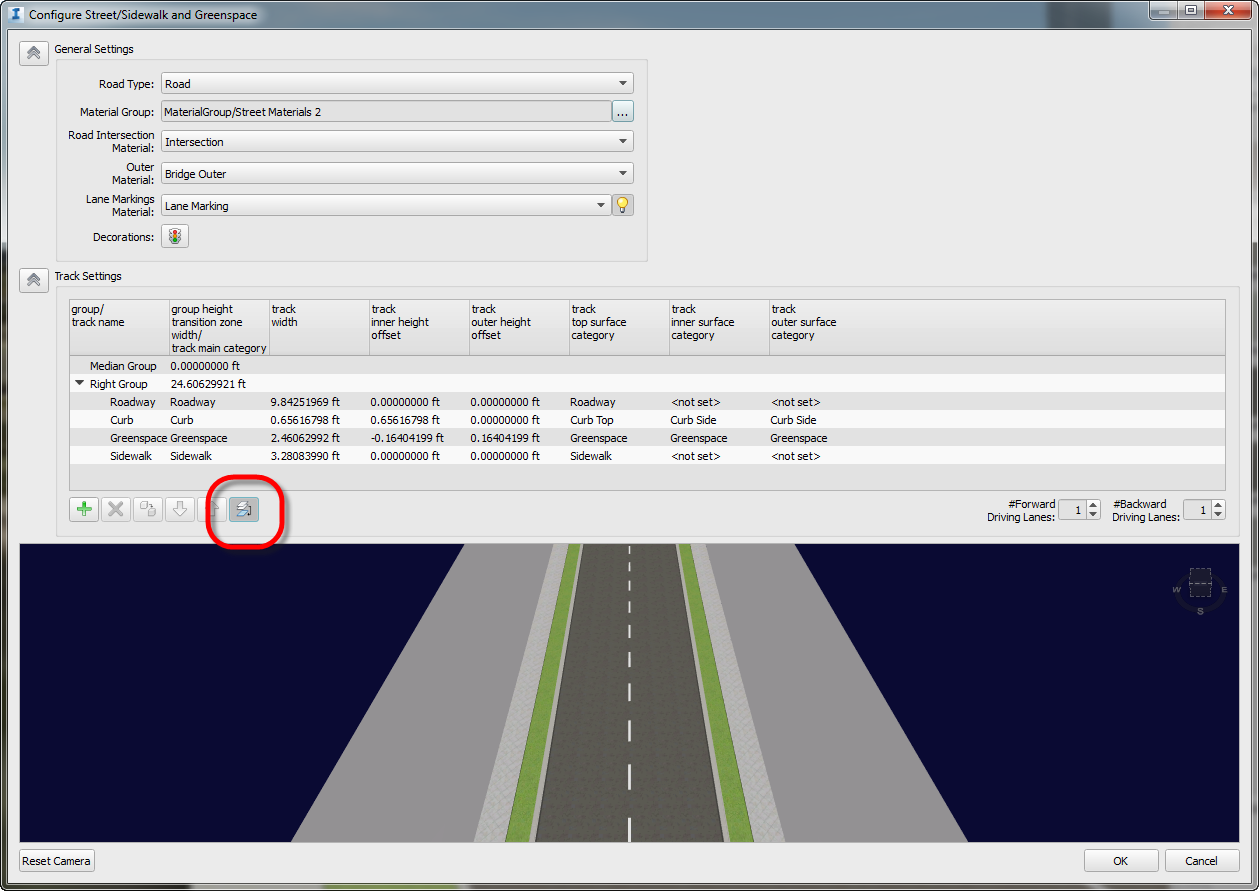
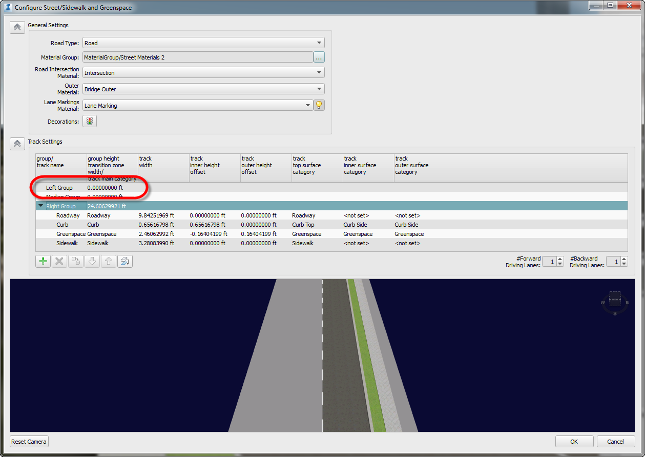
Add text into the interior elevation marks to display a consistent view designation letter on every orientation.
Sometimes, there is a need to dummify Revit to override the default behavior in order to achieve certain tasks. In the case of Interior Elevations, the Mark Arrowheads are hardcoded to report a unique designation in line: Revit cannot have redundant detail numbers in sheets. But we can cheat Revit by adding text into the Interior Elevation Pointer family that displays a consistent view designation to every interior elevation orientation.We would need to customize the Viewport and create a dummy view title using a Generic Annotation to aggregate multiple elevations into a single Title. Learn the workaround as well as the pros and cons of this method in the tutorial on YouTube. 

Cesar Escalante, AIA, LEED AP, CCCA
AEC Solutions Application Specialist

Cesar has a Bachelor of Architecture degree from the University of Central America in El Salvador, a Master of Architecture from the University of Texas, and is a CCCA (Certified Construction Contract Administrator). His experience includes roles as Project Manager and Project Captain at architecture firms in Oakland, California. As a member of the Ideate Tech Expert team, Cesar teaches Revit Architecture Fundamentals and provides client support and consulting. Cesar’s interest in the built environment includes his work as a volunteer for Habitat for Humanity.

Get it. Know it. Use it.


December 29, 2014

eLearning - Upcoming Revit, Navisworks, and Ideate Software Classes


Join the Ideate Tech Experts for eLearning – live online classes that provide your entire organization with easy access to premium education. 
 
12.30::Ideate Software:
Revit Auditing with Ideate Explorer for Revit
12.31::Navisworks 201:
Clash Detection

1.6::
Revit 201
:
Converting Blocks to Families & Working with 2D Content in Revit
1.8::Revit 201:
Working with Wall Types in Revit
Architecture
1.9::Revit 201:
Scheduling 201
 
Each class is designed to give you specific, improved results in a particular topic. You can interact with the instructor right from your own office, while eliminating travel time. Because the class schedule rotates, you can easily select your topics of interest and choose the day which best meets your schedule.

Click here for class descriptions, times and registration link. Questions? Contact education@ideateinc.com

Get It. Know It. Use It.

AutoCAD MEP -- Takeoff Anchors

Consider the simple duct arrangement below. The duct has two takeoffs connected to it. The first was added when a branch was connected to the main run. The second was added independently using the “Add Duct Fittings” dialog (easily done using “Add Selected” with the first takeoff).
 

The takeoffs may look identical but they will be added with a different anchor.

 
Basic Anchor

Select the first takeoff that got inserted with the duct, right-click and choose “Properties” and navigate to the “Anchor” table in the Advanced panel of the dialog. Notice, how you can use this to adjust the position of the takeoff along the duct but not its vertical position. 


Takeoff Position Anchor

If you look at the “Duct Fitting Properties” dialog for the second takeoff that was inserted independently, you have a “Takeoff Position” anchor instead which as some additional options.


Within this dialog, we can set the anchor to position above or below the center of the duct. For example, the second takeoff is now positioned on the “Left” face with a 2 inch offset from the top of the duct:


One point to note; the “Left" ( or Right or Top or Bottom ) side of the duct is relative to the direction that the duct segment was drawn in.


Bill Johnson
Ideate Senior Application Specialist MEP/AEC Solutions

Bill has over 25 years experience in applying MEP & AEC design solutions for large commercial companies, this has led to actively develop Autodesk® Revit® implementation strategies, techniques, and procedures for architectural and MEP companies. He has worked for TEECOM Design Group, GTE/GTEL, Greg LeDoux and Associates, and Scottish Power in England. Bill is a Autodesk MEP Implementation Certified Expert, and has been the Lead Designer for several multimillion dollar communication sites which have included structural, electrical, HVAC, conduit, cable plans and equipment layouts. He graduated from the Pasadena Institute of Technology and has a Sustainable Design Certification from the University of California at Berkeley.

Get it. Know it. Use it.

Classroom Training - Open AutoCAD and Revit Architecture


Know It. Ideate Training.

Position yourself to land dream projects. Tap the full potential of your software solutions. Increase your facility, fluidity and capability to maximize the value of your precision software tools.
1.6-1.8::Seattle
AutoCAD Fundamentals
1.6-1.8::Portland
Revit Architecture Fundamentals
1.12-1.13::San Francisco
AutoCAD Beyond the Basics

1.20-1.22
::San Jose

AutoCAD Fundamentals
1.20-1.22::San Francisco
Revit Architecture Fundamentals

1.21-1.23
::Seattle

Revit Architecture Fundamentals
Know your software. Sign up now!

December 23, 2014

Hidden feature of InfraWorks: How to Create a Non-symmetrical Roadway Section

If you have been using InfraWorks for a while you would know that most roadway styles that come shipped with the software are for symmetrical roadway. There is not enough documentation on how to create a non-symmetric section and it is unintuitive. In this blog post I expose a little trick and this hidden feature.

So here a screen shot of the typical symmetric roadway section.


You want to go from the above to the following – No Passing zone…


Or a bike lane…


Now that I have your attention – here is how you achieve this:

In the Style Edit dialog box the Track Settings frame highlighted in red…


…has a few buttons at the bottom to edit/modify the roadway section. What is apparent is that if you select a row in the Right Group or Median Group and use the above mentioned buttons you can modify section. For example, add/modify lane/sidewalk width, etc.

Here is the important part – what is not apparent is that if you click on the row Right Group, not a row within the Right Group, you end up selecting the whole Right Group and then if you use the last button highlighted in red below…


…you get the Left Group…


Now you can modify this Left Group to create a section per project requirements. In the interest of time and simplicity I completed the left group as shown below. You can see the it has a bike lane.


And that’s it!

Now if you have not customized styles in InfraWorks look for my blog post about how create/modify styles in InfraWorks.


Gaurav Bagga
Ideate Infrastructure Solutions Application Specialist

Gaurav is a well rounded Application Engineer and Project Manager for Infrastructure Solutions at Ideate based out of San Francisco. He has over 15 years experience in construction industry and has been helping numerous small, medium and ENR 500 firms maximize their CAD investment for the last ten years. Gaurav is an Autodesk Certified Instructor and Autodesk Civil 3D Implementation Certified Expert. He has taught at several conferences, CAD Camps and Autodesk University. He has taught AutoCAD, Civil 3D, Land Desktop and Map 3D to thousands of students and helps Ideate develop the Infrastructure Services curriculum and courses. With his extensive CAD technology background he helps Bay Area engineering and surveying firms analyze and improve their design and drawing production process thereby improving productivity and the bottom line. Follow Gaurav on Twitter: @BeGeez

Get it. Know it. Use it.

December 22, 2014

eLearning - Upcoming Revit, Navisworks, and Ideate Software Classes

Join the Ideate Tech Experts for eLearning – live online classes that provide your entire organization with easy access to premium education.
12.23::Revit 201:
Working with Parts in Revit
12.30::Ideate Software:
Revit Auditing with Ideate Explorer for Revit
12.31::Navisworks 201:
Clash Detection

1.6::
Revit 201
:
Converting Blocks to Families & Working with 2D Content in Revit
1.8::Revit 201:
Working with Wall Types in Revit
Architecture
1.9::Revit 201:
Scheduling 201
Each class is designed to give you specific, improved results in a particular topic. You can interact with the instructor right from your own office, while eliminating travel time. Because the class schedule rotates, you can easily select your topics of interest and choose the day which best meets your schedule.

Click here for class descriptions, times and registration link. Questions? Contact education@ideateinc.com

Get It. Know It. Use It.

Classroom Training - Open AutoCAD and Revit Architecture

Know It. Ideate Training.

Position yourself to land dream projects. Tap the full potential of your software solutions. Increase your facility, fluidity and capability to maximize the value of your precision software tools.
1.6-1.8::Seattle
AutoCAD Fundamentals
1.6-1.8::Portland
Revit Architecture Fundamentals
1.12-1.13::San Francisco
AutoCAD Beyond the Basics

1.20-1.22
::San Jose

AutoCAD Fundamentals
1.20-1.22::San Francisco
Revit Architecture Fundamentals

1.21-1.23
::Seattle

Revit Architecture Fundamentals
Know your software. Sign up now!

December 18, 2014

Ideate, Inc. Announces a New Update for Ideate Explorer for Revit

San Francisco, CA, 12/18/2014–Ideate, Inc., a multi-decade veteran Autodesk Developer Network member and Autodesk Gold Value Added Reseller today announced the availability of Ideate Explorer for Revit 2015.1. This Ideate Software solution includes enhanced functionality customers have requested, specifically a modeless interface. Now, users will be able to work in the Autodesk Revit and the Ideate Explorer for Revit environments at the same time. 

Ideate Software is a set of far-reaching Building Information Modeling (BIM) data management tools that help the Revit community clean up models, delete problem items, analyze files quickly, improve speed and accuracy in data flow, increase collaboration and overcome repeated workflow interruptions. 

This recent Ideate Explorer for Revit update provides BIM and Virtual Design and Construction (VDC) managers, project leaders, facility managers, architects, engineers, and other users an enhanced tool for model auditing, power selection and model maintenance. With it, they can get a global view of model contents, and locate, isolate, modify and/or effectively delete unwanted elements from the Revit model.  

Ideate Director of Software Development Glynnis Patterson says, “This new release lets our customers delve both deeply and seamlessly into their Revit files, since they can now work in Revit and Ideate Explorer at the same time. We make sure our BIM data management solutions are robust and our updates meaningful and frequent. This new functionality answers a No. 1 customer request.”

Bob Palioca, President, Ideate Inc. says of the new Ideate Explorer release, “As our AEC customers ask for greater speed and fluidity in our Revit-based solutions, we respond. This point release is another leap forward in our ongoing commitment to our customers’ success.” 

Customers who tested the new functionality offered comments on the most valuable aspect of Ideate Explorer to their workflows. Marcus Roman, Associate/Architect for NBBJ, noted greatest value in “Being able to quickly see elements in the model and identify errors.” Andy Brahney, Senior Revit Technician at Ramboll UK said, “Being able to find which workset elements are on; this helps greatly with the QA process.” And, Dan Dankert, CAD/BIM Manager for Mead & Hunt acknowledged, “Finding lost and incorrect objects.”

Ideate Explorer for Revit carries a five star rating on the Autodesk Exchange Apps Store, and is available with a non-commercial free trial. For more information, call 888.662.7238, contact sales@ideatesoftware.com, and for support, contact support@ideatesoftware.com.

About Ideate, Inc.
Ideate, Inc. is a leading Autodesk Authorized Developer with 25+ years’ experience in software development and specific focus on Building Information Modeling (BIM). As an Autodesk solutions provider, Ideate has offered quality software, training, support and custom consulting services to the architectural, engineering and construction (AEC) industries since 1992. Headquartered in San Francisco, California and operating Autodesk Authorized Training Centers (ATCs) in California, Oregon and Washington, Ideate is recognized as an Autodesk Gold Partner for Architecture, Engineering and Construction, one of Autodesk’s highest levels of authorization. 


Ideate Software is a comprehensive set of far-reaching BIM data management tools. Ideate BIMLink powers the “I” in BIM, allowing users to pull data from an Autodesk Revit file into Microsoft Excel for fast and precise editing, and push the data back into Revit with equal ease. Ideate Explorer for Revit lets users search, filter, quantify and select to easily manage the 100,000+ elements in a Revit model. Both solutions help Autodesk Revit users solve problems in AEC workflows and help the Revit community leverage BIM to its fullest advantage. 

Autodesk, Autodesk Revit and ATC are registered trademarks or trademarks of Autodesk, Inc., and/or its subsidiaries and/or affiliates in the USA and/or other countries. Microsoft Excel is a registered trademark of Microsoft Corporation in the United States and other countries. All other brand names, product names or trademarks belong to their respective holders.

This post was originally published on the Ideate Software Blog.

# # #

December 16, 2014

Average Estimated Illumination and Gradient Color Fill Plans

Using color to fill to indicate value in Revit MEP models can visually convey data in a meaningful way. For example, indicating average illumination with meaningful colors, red for high lux, yellows and oranges for mid lux, and green for low lux can help one make more sense of a model with a quick glance than having to reference and re-reference the legend when using neutral and/or non-ordered color fills. Follow this Revit MEP workflow to customize the color fill in your models. 

Place the color fill legend anywhere in the drawing area to describe the color scheme used in the view. 
  1. Open a floor plan view or section view. 
  2. Click Annotate tab Color Fill panel(Legend). 
  3. Click in the drawing area to place the color fill legend. 
  4. In the Choose Space Type and Color Scheme dialog, select the space type and color scheme, and click OK. 
If the color fill legend that displays does not reflect the color scheme that you want to use, do the following: 
  1. In the drawing area, select the legend. 
  2. Click Modify Color Fill Legends tab Scheme panel Edit Scheme. 
  3. In the Edit Color Scheme dialog, select a different color scheme from the list, and click OK. 
You can also create a new color scheme in this dialog. 

In the illustration below is a typical Average Illumination color fill in Revit MEP. Although the legend indicates the lux level next to a color, the range of colors used is not particularly indicative of the value. 
A better representation would be to use a range from green, through yellow to red, as illustrated with this alternative color fill where green rooms have a low lux level and red rooms have a high lux level, and yellow is used for the mid-range: 
This can simply be set up by manually assigning colors using an RGB value. Let’s take a look at the RGB values of green, yellow and red: 
In order to change from green to yellow, we simply increase the R value incrementally from 0 to 255, then to change from yellow to red we simply decrease the G value from 255 to 0. Let’s consider a lux level range from 0 to 500+ and interpolate the appropriate RGB values: 
These can then be easily assigned to the Color Fill in the Edit Color Scheme dialog:
For more information visit our website at www.ideateinc.com


Bill Johnson
Ideate Senior Application Specialist MEP/AEC Solutions

Bill has over 25 years experience in applying MEP & AEC design solutions for large commercial companies, this has led to actively develop Autodesk® Revit® implementation strategies, techniques, and procedures for architectural and MEP companies. He has worked for TEECOM Design Group, GTE/GTEL, Greg LeDoux and Associates, and Scottish Power in England. Bill is a Autodesk MEP Implementation Certified Expert, and has been the Lead Designer for several multimillion dollar communication sites which have included structural, electrical, HVAC, conduit, cable plans and equipment layouts. He graduated from the Pasadena Institute of Technology and has a Sustainable Design Certification from the University of California at Berkeley.

Get it. Know it. Use it.

December 15, 2014

Phase Mapping Linked Revit Models in the Plan

Recently we had a support case here where all of the Phases were showing up in plan from a linked Revit Model and not being controlled by the current View setting in the Primary Model. The Primary Model and the Linked Model were created from the same Template with 6 Phases created with the same name in each. All of the Model elements were in the correct Phase and the all the Views were set to see only the Phase needed for that part of the project. What went wrong? Phase Mapping.
 

View the Autodesk Revit Help files for issues with phase mapping linked Revit models.

Also, for information on training and consulting for the various products Ideate services, visit our website at www.ideateinc.com


Bradley Cooley
AEC Application Specialist

Bradley earned his Bachelor of Architecture degree from the University of Oregon, the Portland, Oregon campus, where his special research and design emphasis was on commercial production facilities including wineries, breweries and distilleries. Bradley’s professional experience has a design focus on build services for residential construction and environmental graphics. Within his community, he volunteers as a youth athletics coach. As Ideate's Services Manager and a Revit Instructor, Bradley provides Revit MEP training and support for AEC firms. He is based in the Ideate Portland, Oregon office.

Get it. Know it. Use it.

eLearning - Upcoming Revit, Navisworks, Civil 3D, and Ideate Software Classes

Join the Ideate Tech Experts for eLearning – live online classes that provide your entire organization with easy access to premium education.
12.18::Revit 201:
Getting Started with Presentations in Revit Architecture
12.19::Infrastructure 201:
Intersection Design Tool

12.23::
Revit 201
:
Working with Parts in Revit
12.30::Ideate Software:
Revit Auditing with Ideate Explorer for Revit
12.31::Navisworks 201:
Clash Detection
1.6::Revit 201:
Converting Blocks to Families & Working with 2D Content in Revit
Each class is designed to give you specific, improved results in a particular topic. You can interact with the instructor right from your own office, while eliminating travel time. Because the class schedule rotates, you can easily select your topics of interest and choose the day which best meets your schedule.

Click here for class descriptions, times and registration link. Questions? Contact education@ideateinc.com

Get It. Know It. Use It.

Classroom Training - Open Revit Architecture and AutoCAD Classes

Know It. Ideate Training.

Position yourself to land dream projects. Tap the full potential of your software solutions. Increase your facility, fluidity and capability to maximize the value of your precision software tools.
1.6-1.8::Portland
Revit Architecture Fundamentals
1.6-1.8::Seattle
AutoCAD Fundamentals
1.12-1.13::San Francisco
AutoCAD Beyond the Basics

1.20-1.22
::San Jose

AutoCAD Fundamentals
1.20-1.22::San Francisco
Revit Architecture Fundamentals

1.21-1.23
::Seattle

Revit Architecture Fundamentals
Know your software. Sign up now!

December 8, 2014

Classroom Training - Open AutoCAD and Revit Architecture Classes

Know It. Ideate Training.

Position yourself to land dream projects. Tap the full potential of your software solutions. Increase your facility, fluidity and capability to maximize the value of your precision software tools.
12.11-12.12::San Francisco
AutoCAD Beyond the Basics
12.16-12.18::San Francisco
Revit Architecture Fundamentals

1.6-1.8
::Seattle

AutoCAD Fundamentals

1.6-1.8::Portland
Revit Architecture Fundamentals
1.13::San Francisco
Revit Architecture Families
Know your software. Sign up now!

eLearning - Upcoming Revit, Navisworks, Infrastructure, and Ideate Software Classes

Join the Ideate Tech Experts for eLearning – live online classes that provide your entire organization with easy access to premium education.
12.9::Ideate Software:
Revit Project Management with Ideate BIMLink
12.11::Revit 201:
Revit MEP and Low Voltage Systems


12.18::
Revit 201
:
Getting Started with Presentations in Revit Architecture
12.19::Infrastructure 201:
Intersection Design Tool
12.23::Revit 201:
Working with Parts in Revit
12.30::Ideate Software:
Revit Auditing with Ideate Explorer for Revit
12.31::Navisworks 201:
Clash Detection
Each class is designed to give you specific, improved results in a particular topic. You can interact with the instructor right from your own office, while eliminating travel time. Because the class schedule rotates, you can easily select your topics of interest and choose the day which best meets your schedule.

Click here for class descriptions, times and registration link. Questions? Contact education@ideateinc.com

Get It. Know It. Use It.

December 4, 2014

Using Filters to Hatch Cable Tray in Revit MEP

Display Filters & View Templates

In many system drawings there is a need to differentiate between different types of Cable Tray elements in coordination and dedicated electrical drawings.
Standard display of the Cable Tray using fine settings from the Electrical-Default template
In traditional CAD this was achieved by using different Layers and although we have similar methodologies in Revit via the System Styles where we can set colors and patterns by category there is often a need to show certain items, like cable tray differently, even though they may be of the same category.

The main reason for this paper is that I was asked today by one of my students, "What is the easiest way to hatch cable tray in Revit MEP to indicate the different types of cable tray that has been installed on a project." There are several ways this could be accomplished. You could simply use the Filled Region to manually hatch the cable tray. While this is the most simple, it is tedious and time consuming.

Method 2 would be to use Phases inside of Revit MEP. You could set up some phases and change the graphics of the phases to indicate the hatching. This is easy enough, but almost an over kill.

The method I ended up recommending is to just use View Filters. You can simply create a new filter and change the graphics of the filter to have the hatch pattern.

To this end I created a short video to share with my students and thought it might be helpful for others. Watch the video Here
.

For more information visit our website at www.ideateinc.com


Bill Johnson
Ideate Senior Application Specialist MEP/AEC Solutions

Bill has over 25 years experience in applying MEP & AEC design solutions for large commercial companies, this has led to actively develop Autodesk® Revit® implementation strategies, techniques, and procedures for architectural and MEP companies. He has worked for TEECOM Design Group, GTE/GTEL, Greg LeDoux and Associates, and Scottish Power in England. Bill is a Autodesk MEP Implementation Certified Expert, and has been the Lead Designer for several multimillion dollar communication sites which have included structural, electrical, HVAC, conduit, cable plans and equipment layouts. He graduated from the Pasadena Institute of Technology and has a Sustainable Design Certification from the University of California at Berkeley.

Get it. Know it. Use it.

December 2, 2014

eLearning - Upcoming Revit, Infrastructure, and Ideate Software Classes

Join the Ideate Tech Experts for eLearning – live online classes that provide your entire organization with easy access to premium education.
12.4::Revit 201:
Roofs in Revit Architecture
12.5::Infrastructure 201:
Section Sheets - Code Set Styles


12.9::
Ideate Software
:
Revit Project Management with Ideate BIMLink
12.11::Revit 201:
Revit MEP and Low Voltage Systems
12.18::Revit 201:
Getting Started with Presentations in Revit Architecture
12.19::Infrastructure 201:
Intersection Design Tool
Each class is designed to give you specific, improved results in a particular topic. You can interact with the instructor right from your own office, while eliminating travel time. Because the class schedule rotates, you can easily select your topics of interest and choose the day which best meets your schedule.

Click here for class descriptions, times and registration link. Questions? Contact education@ideateinc.com

Get It. Know It. Use It.

Classroom Training - Open Revit, AutoCAD, and AutoCAD Civil 3D Classes

Know It. Ideate Training.

Position yourself to land dream projects. Tap the full potential of your software solutions. Increase your facility, fluidity and capability to maximize the value of your precision software tools.
12.8-12.10::San Francisco
Civil 3D Fundamentals
12.9-12.11::Sacramento
Revit Architecture Fundamentals

12.11-12.12
::San Francisco

AutoCAD Beyond the Basics

12.16-12.18::Seattle
Revit Architecture Fundamentals
12.6-12.18::San Francisco
Revit Architecture Fundamentals
Know your software. Sign up now!

Pump(k)in' Up!

Halloween provided us inspiration to put our Revit family skills to work. Find the process of creating a fully parametric pumpkin using a single point adaptive component and a divided path. This tutorial was presented at the November 14 Redwood Empire Revit User Group.
 
You can create a parametric pumpkin by nesting a repetitive single point adaptive component into a tiny circular divided path.

It’s always been in the back of my mind every Halloween day. How to create a fully parametric pumpkin? The concept was very simple. Create a single ‘wedge’ component and array it. The challenge was that you can’t create polar arrays as we know it in the Mass environment because the command ‘Array’ simply does not exist here. The other challenge is with partial elliptical profiles. Unlike Arcs and Splines, partial ellipses are rigid to control intuitively because the start and end ‘nodes’ will not reshape the ellipse size after placement. So I had to drive the ellipse size via parameters. 
 
Dragging the ends of a partial ellipse will not change the ellipse size.

I created a polar arrays of components using a divided path on a circle with visible nodes, and nesting a single point adaptive components as a repetitive component, and viola!

Find the explanation along with the video tutorial Here:


Cesar Escalante, AIA, LEED AP, CCCA
AEC Solutions Application Specialist

Cesar has a Bachelor of Architecture degree from the University of Central America in El Salvador, a Master of Architecture from the University of Texas, and is a CCCA (Certified Construction Contract Administrator). His experience includes roles as Project Manager and Project Captain at architecture firms in Oakland, California. As a member of the Ideate Tech Expert team, Cesar teaches Revit Architecture Fundamentals and provides client support and consulting. Cesar’s interest in the built environment includes his work as a volunteer for Habitat for Humanity.

Get it. Know it. Use it.