Showing posts with label Autodesk authorized reseller. Show all posts

May 12, 2016

Revit 2017 Text Size Changes

You may have heard that the measurement of text sizes is changing in Revit 2017.

The Revit 2017 “Upgrade Information for Revit 2017” help topic offers the following explanation:

“The method for measuring text size is changed so that the Text Size parameter more accurately represents the height of a capital letter (similar to AutoCAD). Previously, Revit measured the size of text from the font baseline to the ascender line. Since most characters do not extend to the ascender line, physically measuring the font may not have produced expected results.

The size of text now reports using the cap height, which measures from the baseline to the top of a capital letter M as seen in the image below. This change affects all text in Revit. After upgrading a model, please review all views and sheets to verify the changes to your text instances.”
 This evokes two practical questions:
  • Does my text get larger or smaller when upgrading to Revit 2017?
  • How much larger or smaller does my text get?
And here are the short answers:
  • The rendered text gets larger when upgrading to Revit 2017 from earlier versions.
  • How much larger? Well, that depends!
Let’s investigate using a simple example with then ¼” Calibri text style in a Revit text note. (With apologies to our metric friends in the rest of the world of course!)

I’ll use the letters “MhO” (coincidentally the acronym for My humble Opinion) to illustrate the intricacies of text size measurements. I’ll also draw some surrounding rectangles to help measure and compare letter sizes.

First, the text note in Revit 2016:

¼” Calibri Text Note - Revit 2016
Note that even though this is ¼” text, no part of the letters (width or height) measures ¼”.

Also note how the lower case ‘h’ is a smidge taller than the capital ‘M.’

For some fonts, such as Calibri, the height of letters such as English lower case ‘h’ (called the ascender height) is a bit higher than the capital letter ‘M’ (called the cap height). In other fonts, such as Arial, the height of ‘h’ and ‘M’ are the same.

This height difference is the heart of the text measurement change made in Revit 2017:
  • In Revit 2016 and earlier, text size is measured by the ascender height – the height of lower case letter ‘h.’
  • In Revit 2017 size is measured by the cap height – the height of the capital letter ‘M.’
However, this isn’t the whole story. Notice that in Revit 2016, the ‘h’ isn’t quite ¼” tall as one would expect from the Revit help explanation. So in actuality, the height of Revit 2016 and earlier text seems to be based on the height of ‘h’ and a bit more.

Now, let’s take that “MhO” drawing from Revit 2016 and upgrade it to Revit 2017.

¼” Calibri Text Note - Revit 2017 (upgraded from Revit 2016)
The upgraded to 2017 text is larger, as expected, but it has also been moved down the page a bit. In fact, the top of the ‘h’ now aligns with where the top of the ‘M’ was in the 2016 project.

To do a better size comparison, let’s realign the bottom of the measurement rectangle to the bottom of then ‘M’ as it was originally in Revit 2016.

¼” Calibri Text Note - Revit 2017 (Realigned to 2016 Measurement Lines)
That’s better. Now, as promised by Revit help, the text height of the ‘M’ is the same as the Revit text size. 

More importantly, notice that even for this small stretch of 3 letters, the overall width of the 2017 text note is at least a ½ letter wider than the original 2016 text note. This is expected, because as the text size increases in width it must proportionally increase in width.

From empirical measurements I’ve found Arial about 2% larger and Calibri about 18% larger in text upgraded to Revit 2017. Other fonts will vary depending on the height of ‘h’ versus ‘M.’

Now let’s examine a more realistic example, Arial text notes on a sheet. The example below highlights the visual differences, showing Revit 2016 in red overlapped with Revit 2017 in green:

Sheet Text – 2016 (Red) vs 2017 (Green)
Notice how the green 2017 text in the detail text notes and title block is larger and sometimes wraps to an additional line.

So here are the takeaways for Revit text when upgrading to Revit 2017:
  • All text gets larger in height and width
  • The text gets larger by the ratio of the height of the letters ‘h’ to ‘M’ and a bit more
  • How much text gets larger depends upon the font – perhaps anywhere from 2% to 20% taller and wider
  • Text will shift down a wee bit
  • Text wrapping may cause larger 2017 text to flow onto additional lines


Ben Bishoff
Senior Software Developer
Ben has been a software engineer for over 25 years. With a Bachelor’s degree in Physics, he has worked at several software companies developing applications for the AEC industry including Sage Timberline (construction accounting and estimating) and ArchT (architectural drafting for AutoCAD). He also worked at Microsoft creating AEC and other diagramming solutions for Office Visio. Ben has been with Ideate Software for over 8 years developing add-ins for Revit including Ideate Explorer and Ideate BIMLink.


This article was originally posted on the Ideate Software blog.


March 15, 2016

New Director of Marketing to Lead Client-Focused Activities

Ideate, Inc. is pleased to announce that Qatanna Palioca has been named Director of Marketing. Qatanna joined Ideate four years ago, and she has been instrumental in developing innovative marketing campaigns that highlight the unique value that Ideate provides. As Director of Marketing, she will play a significant role in helping Ideate achieve its goals of delivering thought leadership presentations, developing the Revit community, and informing clients of industry trends and activities. 

Director of Marketing - Qatanna Palioca
In addition to leading the marketing activities of Ideate, Inc., Qatanna will oversee all marketing activities of Ideate Software, which develops Autodesk Revit add-on solutions that enable Revit users to save time, increase accuracy, improve project deliverables, and elevate design.

You can reach Qatanna at qatanna.palioca@ideateinc.com.

March 8, 2016

Autodesk Ideas Page

While on tech support at Ideate Inc., I often hear people articulating a new function or feature for an Autodesk product. These suggestions spawn from frustration and inspiration alike. They often come in the form of “I wish the software worked like this.” It turns out there is a place to voice these ideas. It is called the Ideas Page.

The Ideas Page is a part of the knowledge network and is a great place to communicate concerns as well as pitch ideas. If you have an idea, you can check out the site to see if it’s already been submitted. If it has, you can endorse the idea by liking it. The more endorsements an idea gets, the higher the likelihood it will be incorporated into a future release of the product. Occasionally, someone will comment on a post giving work-arounds for the current release.

Check out the Ideas Page. It is one of the ways Autodesk allows customers to give feedback. If you ever have an idea for a feature or function with in a program, I recommend posting it to the Autodesk Ideas Page.

For information on training and consulting for the various products Ideate services, visit our website. Also, check our blog for continued solutions as we encounter them.


Kate Ming
AEC Application Specialist
Kate is a California licensed civil engineer with a BS in Civil and Environmental Engineering from UC Berkeley. Prior to Ideate, she worked at a multinational company for four years doing general civil design on large infrastructure projects. She is versed in roadway, rail, utility design and site development. She also has experience with utility demand analysis and Low Impact Development plans. As a Civil 3D Autodesk Certified Professional Kate provides training and support for Civil 3D, AutoCAD, and InfraWorks.

March 7, 2016

Wrapping Your Head Around Wall Wraps

I was talking to Eugene O’Day, one of my Ideate colleagues and a contributor to the Ideate Solutions blog, regarding an issue he was running into with controlling the wrapping of wall layers at the insertion of a door or window within a wall. What he was looking for, was a way to control the distance a wall layer would wrap around the wall where a door or window was inserted.


Wall Wrap at Door/Window Insertion
By default, the System Family: Basic Wall allows you control how wall layers are wrapped around a wall where a door or a window have been inserted. The default option is Do not wrap. Options include: Do not wrap, Exterior, Interior, and Both.
Default Wall Wrapping at Inserts Options
When an option is chosen, the wall layers on that appropriate side, wrap around the wall and stop at the wall centerline. For example, if the Exterior option is chosen, all wall layers on the exterior side of the wall will wrap around the end of the wall and stop at the wall centerline.


Default Exterior Wall Wrapping Stops At Wall Centerline
The default options are great as a starting point, but if you would like to control the distance the exterior or interior wall layers’ wrap around the end of the wall, then you will need to modify the door or window family. Door and window families control the wall wrap of the wall they are inserted into.

When working with a door or window family, the simple use of reference planes and their “Wall Closure” parameter is used to control where the wall layers stop. If you need to control both the exterior side and the interior side wall wrap, draw two reference planes inside the wall found in the door and window family. Draw the reference planes across the door or window opening. Next select the reference planes and in the Properties Palette turn on the Wall Closure parameter. Additionally, consider naming the reference planes for future editing. I like to name my reference planes so that I can later come back and decipher what it was that I was doing. In this case, I named the exterior side reference plane “ Ext Wrap” and the interior side reference plane “Int Wrap” accordingly.


Create reference planes to represent where the wall layers will stop.
Assign each reference plane to the Wall Closure parameter.
Wherever you draw the reference plane(s), the wall layers will now stop at that point when a wall is set to wrap at the inserts. Should you wish to control the distance of the wall wraps from the edges of the wall, you will need to add parameters to make the reference planes parametric.

When adding dimensions to each wall closure reference plane, start the dimension from the outside edge of the wall, to the reference plane. This uses the outer edge of the wall as the controlling dimension edge and causes the reference plane to be adjusted when the dimension value is changed.
 
Dimension the location of the wall closure reference planes.
Select the outside edge of the wall first then the reference plane.

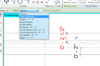
After the wall edges and wall closure reference planes have been dimensioned parameters can be assigned. Select one of the dimensions and in the Options bar select.

Select a dimension, go to the Label drop-down
and choose Add Parameter.
In the Parameter Properties dialog box, create a new parameter. In this example I have named the dimension controlling the exterior wrapping reference plane Exterior Wrap. Notice too that I have selected the Instance type of parameter. The reason I chose Instance was that I could use the same door type in a number of different wall types that had varying wall layer thicknesses. If a Type parameter is used, then different types of doors would be needed for the various types of wall the door family would be inserted into. Of course which parameter type you choose is up to you and your workflow.


Create a new parameter for the dimension.
Repeat the steps to create a parameter for the interior wall wrap dimension. Both wall closure reference planes have been dimensioned and parameterized.

Wall wrap parameters have been assigned.
After the door or window family has been created with the wall closure reference planes, dimensions and parameters, save the family. Load the family into the project.

In order to see your results, create a wall. Select the wall type and in the Properties Palette select the Edit Type button. In the Type Properties dialog box change the Wrapping at Inserts parameter to “Both.”


Change the Wrapping at Inserts parameter to “Both.”
Next, insert the door or window into the wall. If you had created the wall wrap parameters as an instance based parameter, in Properties, the parameters are available for you to control the distance the wall layer wrap
Enter the desired wall wrap distance.
If everything was done correctly, you should have a door or window family where you can control the wall layer wrap, providing a more accurate representation of the design intent. Unfortunately, this technique only applies to the wall wrap where door and window families have been inserted. 

Now that you have your head wrapped around wall wraps, go out and modify your door and window families. Until the next time, have fun with wall wrapping. 

If you would like to check these new features out or see what else is new in Revit 2016, take a look at my, and my colleagues videos on the Ideate, Inc. YouTube page.   

For more information on training and consulting for the various products Ideate services, visit our website at www.ideateinc.com


Ron Palma
AEC Application Specialist
Ron has over 24 years of experience in the architectural industry as a drafter, designer, lead project designer, trainer, and a CAD manager implementing Autodesk Architectural Solutions for a residential design firm. His instructional background includes being an Autodesk Certified Instructor (ACI), trainer, support technician, educator at Portland and Clackamas Community Colleges, as well as a U.S. Army certified instructor where he was a senior instructor at Ft Lewis Washington. Ron is a member of the Oregon Army National Guard, where he is a platoon sergeant specializing in training and mentoring soldiers in their careers. Ron is a published writer and continues to author professional technical training manuals and shorts for AutoCAD, AutoCAD Architecture, and Revit. As an Autodesk Certified Instructor and Revit Architecture Autodesk Certified Professional, Ron provides Revit Architecture and AutoCAD training and support for AEC firms. Find him on Twitter.