May 31, 2011

Get Noticed. Get Autodesk Certified!

Autodesk is sponsoring a Certification day on Thursday June 2nd with special pricing of $25 per exam ($50.00 - $175.00 savings!). Users can test at both Ideate San Francisco and Seattle offices.

An Autodesk certified credential signifies that you’ve joined an elite group of experienced design professions from around the world who know how to optimize Autodesk software. There are different levels of Certification available that can lead to accelerated professional development, improved productivity, and enhanced credibility in your field.

Ideate is an Autodesk Authorized Certification Center offering Associate and Professional level certification for AutoCAD, AutoCAD Civil 3D, 3ds Max Design and Revit Architecture.

For more information email education@ideateinc.com or call 888.662.7238 x1012.

Get it. Know it. Use it.

Classroom Training - Open Classes + $200 Off Training with Ideate

Know It. Ideate Training.

Position yourself to land dream projects. Tap the full potential of your software solutions. Increase your facility, fluidity and capability to maximize the value of your precision software tools.

Here are a few of the training opportunities Ideate has to offer in the coming days:
6.2-3::Portland
Revit Architecture Beyond the Basics
6.8-10::Portland
Revit Architecture Fundamentals

Know your software. Sign up now!

Know It. Savings.

Ideate subscription clients who have or renew their Autodesk software subscriptions are eligible to save $200 on training on one Fundamentals or Advanced class. Training must be purchased by 7.31.2011. Course must be completed by 12.16.2011. Read all the details here.

May 27, 2011

Display of Hidden Lines: Revit Structure

One of my students in a recent Revit Structure class had a great question: She was noticing that in some views the walls below the slab would not be visible but in some other views they would be displayed as hidden lines - Why?

The answer turned out to be the ‘Discipline’ that each view was set to; In the view that displayed hidden lines, the view discipline was set to ‘Structural.’ 


Further explanation from Autodesk Wiki help site:
Revit controls the appearance of structural concrete components that are in a hidden state in a view. The appearance of invisible lines of walls, floors, framing, columns, and foundation elements are controlled by the following view parameters:
  • Discipline must be set to Structural to represent invisible lines as hidden.
  • Visual style must be set to either Hidden or to Shaded (select Show Edges on the Graphic Display Options dialog) to represent invisible lines as hidden.


Shruti Harve,

LEED AP, AEC Solutions Application Specialist

Shruti holds a Master of Science degree in Architectural Computing from University of Strathclyde, United Kingdom and is LEED accredited. Her experience includes working in Architecture and Construction firms in India and the United Kingdom as well as Structural Engineering firms in the Bay Area providing design, 3D modeling and drafting services. At Ideate, Shruti provides training and support for Revit Architecture, Revit Structure, 3ds Max, Ecotect and AutoCAD Architecture.

Get it. Know it. Use it.

May 26, 2011

eLearning – Upcoming Revit Classes

Join the Ideate Tech Experts for eLearning - live online classes that provide your entire organization with easy access to premium education. 

Upcoming classes include:
5.31.11::Revit 201: Impressions
6.7.11::Revit 201: Converting Blocks to Families
6.14.11::Revit 201: Revit Architecture Update 2012
Each class is designed to give you specific, improved results in a particular topic. You can interact with the instructor right from your own office, while eliminating travel time. Because the class schedule rotates, you can easily select your topics of interest and choose the day which best meets your schedule.

Click here for class descriptions, times and registration link. Questions? Contact education@ideateinc.com

Get It. Know It. Use It.

May 25, 2011

Revit Architecture 2012 Recent Q & A

I received a few questions after my recent What's New in Revit Architecture 2012 presentation and I thought a blog post would be a great way to share the information.

Q: What is the maximum number of points in a point cloud that is allowed to be imported into Revit?

A: Good question, unfortunately, the maximum number of points allowed in a point cloud file within Revit has not been listed at this time; however we could take hints from AutoCAD and Civil 3D - these programs support two billion points within the point cloud file.

Q: When importing/linking DWG files, are there mapping tools available to map over layers, linetypes, text styles, dimension styles, etc. to Revit equivalents?

A: At this time, the only thing that can be mapped from DWG files being imported/linked into Revit are the line weights assigned to the colors of the layers. In the Insert tab under the Import panel, select the Import Line Weights arrow button in the Import panel title. This will open the Import Line Weights dialog box where you can specify which Revit Line weight to be mapped to a dwg color being imported.

Q: With the new rounding functionality, can you round say 234 to 230 not decimals?

A: The Round(x) function return a number rounded to the nearest whole number. It doesn’t take into consideration rounding direction (round up or down). The Roundup function will round the returned value up to the nearest whole number, where the Rounddown function will round the returned value down to the nearest whole number.

Q: Companies typically schedule floor finishes in a room schedule. When using the Parts tool to designate floor finish materials the floor parts remain disconnected from the room schedule? Will it be the same with ceilings?

A: Yes this is true. The Parts tool is used to create individual parts/pieces from each "layer" within a layered structure such as a wall, floor, roof or ceiling. These parts can then be scheduled using the Schedule/Quantites tool or the Material Takeoff tool. Additionally they can be added to an Assembly where schedules and diagrams can be generated to create "shop" drawings.

Q: What is Family Instance Regeneration? What operations are Multithreaded?

A: Family Instance Regeneration is the ability of regenerating only the single instance of a family being edited, then re-imported into the project file. In previous versions, editing an instance and re-importing would regenerate all instances of the family type that had been modified. The loading of elements into memory are multi-threaded reducing view open times when elements are displayed for the first time in a session.

Q: Your example with Floors and Breaking out PARTS would be ideal for Floor Pattern Plans. It seems to be "per view" but when you did it, it showed up in both 3D and floor plan, can you explain how you did that?

A: When a part is generated from a layered element, the original layered element still remains in the drawing. The parts generated from each layer are elements "overlaid" over the layer they are dependent upon. Visibility Graphics controls whether or not the parts generated in a view are display or not. If Parts are turned on in a particular view, the original supporting object is turned off in that view. So although we created parts in a floor plan view, the 3D view's Visibility Graphic settings had parts turned on which is why the parts appeared in the 3D view.

Q: When Detaching from Central, can a workset be Detached and later re-attached multiple times?

A: Yes. Once a Central file has been detached and worksets removed, the file can be turned into a workshared file again with new worksets. It can later be detached too. It is important to understand that when detaching from a central file and removing the worksets, that you will be losing the defined worksets and the objects assigned to those worksets will no longer be assigned to a workset. You will need to re-assign them to a workset if you choose to create a new work shared file.

Q: When using the Part tool, do the sub-divided parts add to the file size? Is the underlying floor slab sub-divided as well or kept as a single element?

A: Parts will contribute to an increase in file size although not significantly. You have to remember that the original assembly is still within the model, and we are generating "parts" from each layer. When a part is subdivided, underlying parts are not subdivided. Only the part or "layer" that was selected for dividing is split into smaller subsections.

Q: Will this presentation be recorded for replay or repeated?

A: Our presentations are recorded and will be played again in the future. Please stay tuned to our website: www.ideateinc.com for more information. We will be repeating this broadcast over the next few months.

Q: Is there an easy way to create clay tile roof?

A: If you are talking about modeling the roof with each tile, it is the same old way you would approach modeling a project. Probably with component families and in-place families. If you are talking about the appearance of a tile roof, fill patterns and renderable bitmaps can be applied to a roof type to generate a tile roof.

Q: Can 2012 also tag doors in a linked model?

A: The Revit 2011 version did provide the ability to tag walls, doors, windows, structural elements, and furniture to name a few. The 2012 version allows you to tag rooms, spaces, beams, keynotes, beam systems and areas.


Ron Palma
AEC Solutions Application Specialist

Ron has 23+ years of experience in the AEC industry as a designer, lead project designer, trainer and CAD manager. His instructional background includes Autodesk Certified Instructor, trainer, support technician, educator at Portland Community College and Clackamas Community College, and a U.S. Army certified instructor. Follow Ron @RonPalmaAEC.

Get it. Know it. Use it.

May 24, 2011

Delete Unused Styles from Your Civil 3D Drawing

Ideate Inc.’s own Gaurav Bagga explains it on his blog.

While you’re there, be sure to subscribe: http://bimcivil.com/

About Gaurav:


Gaurav Bagga

Infrastructure Solutions Application Specialist


Gaurav is a well rounded Application Engineer and Project Manager for Infrastructure Solutions at Ideate based out of San Francisco. He has over 15 years experience in construction industry and has been helping numerous small, medium and ENR 500 firms maximize their CAD investment for the last ten years. Gaurav is an Autodesk Certified Instructor and Autodesk Civil 3D Implementation Certified Expert. He has taught at several conferences, CAD Camps and Autodesk University. He has taught AutoCAD, Civil 3D, Land Desktop and Map 3D to thousands of students and helps Ideate develop the Infrastructure Services curriculum and courses. With his extensive CAD technology background he helps Bay Area engineering and surveying firms analyze and improve their design and drawing production process thereby improving productivity and the bottom line. Follow Gaurav on Twitter: @BeGeez


Get it. Know it. Use it.

Classroom Training - Open Classes + $200 Off Training with Ideate

Know It. Ideate Training.

Position yourself to land dream projects. Tap the full potential of your software solutions. Increase your facility, fluidity and capability to maximize the value of your precision software tools.

Here are a few of the training opportunities Ideate has to offer in the coming days:
6.1-3::Seattle
AutoCAD Fundamentals
6.1::San Francisco
BIM Management for Revit Architecture
6.2-3::Portland
Revit Architecture Beyond the Basics
Know your software. Sign up now!

Know It. Savings.

Ideate subscription clients who have or renew their Autodesk software subscriptions are eligible to save $200 on training on one Fundamentals or Advanced class. Training must be purchased by 7.31.2011. Course must be completed by 12.16.2011. Read all the details here.

May 23, 2011

Data Reduction for Civil 3D from @eagle_point


Ideate, Inc. is proud to offer Eagle Point Data Reduction for Civil 3D:

Streamline the AutoCAD® Civil 3D® survey transfer process.

Whether you are downloading directly from the collector or importing a job already on the PC, shots described in the field using Eagle Point’s popular coding methodology come into Civil 3D with proper description key symbology and linework automatically generated.

Visit ideateinc.com/products/eaglepoint to learn more.

Get it. Know it. Use it.

May 20, 2011

Revit Viewer - BEWARE


We had a rough support case yesterday that we thought we’d share with everyone in an effort to prevent further headaches. Revit 2012 products automatically install with a new item called the Revit Viewer. You will not see this listed as an installation option during standalone installation nor will this display as a separate item within your control panel. It appears that this may actually be the Revit version of a profile; the shortcut Properties show a “/viewer” switch within the Target as shown.


Yesterday’s support case involved a customer who must have inadvertently launched this version of the software and then proceeded to work for a long time. When it came time to save this customer was unable to do so. Unfortunately, there is no way around this dilemma. Note that when you enter this mode it does warn you that you are working in “Viewer” mode and that you won’t be able to save. While the idea of the Viewer may be a good one, it’s not obvious to us why it would ever install as part of a licensed installation. It’s also disappointing that this new installation behavior is not identified anywhere during the installation. Be careful out there!

Glynnis Patterson,
N.C.A.R.B. – Director of Services

Glynnis is a Registered Architect and has worked within the BIM industry since 1998. A graduate of Carnegie Mellon University, she has worked as an architect, educator and construction site manager. Glynnis is currently the Director of Development Services at Ideate, Inc. and continues to work with AEC clients across the nation, developing, and implementing best practices solutions. In her spare time Glynnis is a member of the Morristown Environmental Commission and builds Lego projects. @GVPinNJ

Get it. Know it. Use it.

May 19, 2011

eLearning – Upcoming Revit Classes

Join the Ideate Tech Experts for eLearning - live online classes that provide your entire organization with easy access to premium education.

Upcoming classes include:
5.31.11::Revit 201: Impressions
6.7.11::Revit 201: Converting Blocks to Families
Each class is designed to give you specific, improved results in a particular topic. You can interact with the instructor right from your own office, while eliminating travel time. Because the class schedule rotates, you can easily select your topics of interest and choose the day which best meets your schedule.


Click here for class descriptions, times and registration link. Questions? Contact education@ideateinc.com

Get It. Know It. Use It.

May 18, 2011

Interior Elevations Done Right in Revit

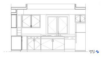
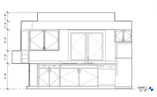
Have you created an interior elevation in Revit, only to have the cropping boundary show everything inside of a rectangular opening? We all know that the Crop boundary is a rectangular boundary that ends up containing the elements we see in a sheet. The issue however is that when we create Interior Elevations we tend to create our own boundary that follows the interior edges of a space. Well, you have stopped by the right place, you can re-create this look through the use of a masking boundary. Figure 1:


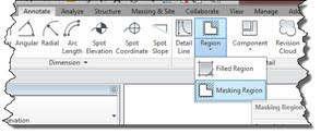
The first thing to do is generate your interior elevations. Figure 1 displays what will be displayed within the cropping boundary. After your Interior elevations have been created, access the Annotate tab; in the Detail panel select the drop-down arrow under the Region tool and choose the Masking Region tool. Figure 2:


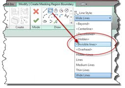
In the Modify|Create Masking Region Boundary tab select the Line Style from the Line Style panel. Figure 3. Draw a rectangular shape around the cropping boundary. Although these are invisible lines, they will be displayed while in Sketch Mode.
Figure 3:


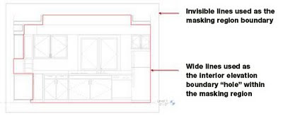
Next select your Line shape and choose Wide Lines (or your own desired Line Style) from the Line Style drop-down list. Draw the desired boundary around your room ensuring that you are outlining your soffits, casework, and anything else desired to form a closed boundary inside of your overall invisible line rectangle. This interior closed boundary “cuts” a hole in the middle of the mask displaying the model geometry beyond. Figure 4:


When finished creating the mask, press the Finish Edit Mode green check mark tool to finish the sketch. If you still see a rectangular box around your mask, in the View Control Bar at the bottom of the screen pick the Hide Crop Region tool to the left of the “sunglasses” tool. The Interior Elevation should be created and ready for you to add dimensions, text, tags, material tags, and keynotes. Figure 5:


Have fun generating your interior elevations!


Ron Palma
AEC Solutions Application Specialist

Ron has 23+ years of experience in the AEC industry as a designer, lead project designer, trainer and CAD manager. His instructional background includes Autodesk Certified Instructor, trainer, support technician, educator at Portland Community College and Clackamas Community College, and a U.S. Army certified instructor. Follow Ron @RonPalmaAEC.

Get it. Know it. Use it.

May 17, 2011

Classroom Training - Open Classes + $200 Off Training with Ideate

Know It. Ideate Training.

Position yourself to land dream projects. Tap the full potential of your software solutions. Increase your facility, fluidity and capability to maximize the value of your precision software tools.

Here are a few of the training opportunities Ideate has to offer in the coming days:
5.18-20::San Jose
Civil 3D Fundamentals
5.23-25::San Francisco
Revit Architecture Fundamentals
5.24-25::San Francisco
Navisworks Fundamentals
5.24-26::San Jose
Revit MEP Electrical Fundamentals
5.24-26::Seattle
Civil 3D Fundamentals
5.24-26::Seattle
Revit Architecture Fundamentals
Know your software. Sign up now!

Know It. Savings.

Ideate subscription clients who have or renew their Autodesk software subscriptions are eligible to save $200 on training on one Fundamentals or Advanced class. Training must be purchased by 7.31.2011. Course must be completed by 12.16.2011. Read all the details here.

May 16, 2011

Where are Those Missing Dialog Boxes in Revit?

In the last couple of Revit Architecture training classes that I instructed, I was finding that some dialog boxes like the Keyboard shortcuts dialog box would just not show up! I knew they were hiding somewhere, but was unable to make them visible, and that’s when I discovered that these dialog boxes were getting stuck between multiple monitors and to get them to show up I had to do the following:

  1. Press Alt+Spacebar, then M, then any arrow key. The window is now stuck to your cursor.
  2. Move your mouse around to find the missing box!


Shruti Harve,

LEED AP, AEC Solutions Application Specialist

Shruti holds a Master of Science degree in Architectural Computing from University of Strathclyde, United Kingdom and is LEED accredited. Her experience includes working in Architecture and Construction firms in India and the United Kingdom as well as Structural Engineering firms in the Bay Area providing design, 3D modeling and drafting services. At Ideate, Shruti provides training and support for Revit Architecture, Revit Structure, 3ds Max, Ecotect and AutoCAD Architecture.

Get it. Know it. Use it.

May 13, 2011

Revit 2012 and the 3D Mouse

One of the new features with Revit 2012 is the compatibility with 3DConnexion 3D mouse. To be honest, I was apprehensive. I’ve heard great things about the 3D mouse, but I get motion sick if VTENABLE in AutoCAD isn’t set to 6. So, I borrowed one from my husband, who uses Solidworks (imagine our dinner conversations). Anyway he kindly lent me his SpacePilot Pro.

It was very easy to download the driver and they have a tutorial on using the device. Once you go through the tutorial you can practice with the game at the end.

Setting up the Pro is very easy, the buttons can be assigned commands easily. Since I am only testing I didn’t do any modifications to the default commands. The LCD screen allows you to view incoming mail from the mouse and open Outlook from the mouse and you could even get RSS feeds from Autodesk.


The biggest issue off the bat was that I had to use my left hand to run this mouse, but since it’s a new technique, it wasn’t hard and I have my typical mouse for my right hand. Looking at my desk you would wonder what I am doing with all of this equipment, the mice, the iPhone, the iPad, second monitors and laptop – my desk looks like a first-rate technology store.

Inside of Revit I was really amazed how quickly I was able to move through the model. Using the View Cube in Revit the model sometimes goes out of view. With practice use of the 3D mouse you can keep the model in view and stay focused on the area of interest. To me it really had the feel of the avatar inside of Navisworks (without the ability to walk).

Another thing when using a 3D mouse and Revit is that when using 3D orbit, you can select an element and that element becomes the pivot point for the rotate. You have to use the standard mouse to select the element and then the 3D mouse to continue the movement. This is not as big an issue as I thought. First, the 3D mouse moves you through the building with such ease (after much practice in my case) that the selection of an element is almost a non-issue. Second, you fall into a new workflow process quickly that using both mice isn’t a liability. What did I like best? During my learning curve I kept losing the model in the 3D view – there is a button on the 3D mouse that goes directly to the 3D home view. Not to mention that The Pro has buttons that will FIT and go to FRONT and ISO with one button. I can see how this can improve productivity.

The Pro is not meant for travel and I doubt the smaller travel version would even be something that I would travel with. Not due to the size, but who wants to travel with two mice?

Since this is not my mouse I will have to return it and I will do this begrudgingly. Within 2 hours of setting up the mouse and using it in Revit MEP I wonder “Where has this been all my Revit life?”


Lana Gochenauer, LEED AP,
MEP Solutions Application Specialist

Lana has a wealth of real world experience, having used Autodesk products on projects from hospitals to universities, restaurants to corporate office headquarters, from strip malls to tenant fit-up. Most recently she focused on coordination drawings/models with MEP contractors, and fabrication from the model. Lana successfully ran her CAD business and worked as the CAD manager for an international MEP engineering firm in Seattle. Lana is a Certified Autodesk Trainer and NECA certified electrical estimator. Currently pursuing her MBA in Sustainability and based in the Ideate ATC in Seattle, Lana provides training and services for AutoCAD MEP, Autodesk Revit MEP and Autodesk Navisworks.

Get it. Know it. Use it.

May 12, 2011

Seattle and San Jose: You're Invited – Navisworks User Groups Forming

Ideate, Inc. is forming User Groups in Seattle and the South Bay Area to create a forum for customers/users of Autodesk Navisworks to gather and:
  • Meet other users
  • Share with other users best practices, concerns, tips and tricks
  • Learn how others are using Navisworks to solve business problems
It is not only for experienced users, but those Architects/Engineers/Contractors who have interest in what Navisworks and associated collaboration can do for their projects. Come join us for this organizational meeting. We will be discussing the formation of the User Group. This first meeting will be short (only about an hour) and your input will be valuable. Please feel free to pass this invite on to your colleagues!

Seattle: 5.23.11
view invite

South Bay: 5.26.11
view invite

See you there!

Get it. Know it. Use it.

eLearning – Upcoming Revit Classes

Join the Ideate Tech Experts for eLearning - live online classes that provide your entire organization with easy access to premium education.

Upcoming classes include:
5.17.11::Revit 201: Rapid Detailing
5.31.11::Revit 201: Impressions
Each class is designed to give you specific, improved results in a particular topic. You can interact with the instructor right from your own office, while eliminating travel time. Because the class schedule rotates, you can easily select your topics of interest and choose the day which best meets your schedule.


Click here for class descriptions, times and registration link. Questions? Contact education@ideateinc.com

Get It. Know It. Use It.

May 11, 2011

AutoCAD MEP Conduits Not Appearing Correctly in Revit MEP?

We recently had an issue in support where conduits drawn in AutoCAD MEP were not showing up correctly when linked in Revit MEP. It appeared that the conduits were coming into Revit as wireframe and at the connections appeared to “twist” in orientation, not displaying a round connection.

Figure 1


To address this issue, within AutoCAD MEP enter the command CONVERTTO3DSOLIDS and select the conduit to convert the conduit into an AutoCAD solid. Once this is done, link the file back into Revit and the conduit will appear correctly.

Figure 2


Ron Palma
AEC Solutions Application Specialist

Ron has 23+ years of experience in the AEC industry as a designer, lead project designer, trainer and CAD manager. His instructional background includes Autodesk Certified Instructor, trainer, support technician, educator at Portland Community College and Clackamas Community College, and a U.S. Army certified instructor. Follow Ron @RonPalmaAEC.

Get it. Know it. Use it.

May 10, 2011

Classroom Training - Open Classes + $200 Off Training with Ideate

Know It. Ideate Training.

Position yourself to land dream projects. Tap the full potential of your software solutions. Increase your facility, fluidity and capability to maximize the value of your precision software tools.

Here are a few of the training opportunities Ideate has to offer in the coming days:
5.13, 20, 27::San Francisco
Revit Architecture Fundamentals
5.16-17::San Francisco
Ecotect Fundamentals
5.17-19::Sacramento
Revit MEP Electrical Fundamentals
5.18-20::San Jose
Civil 3D Fundamentals
Know your software. Sign up now!

Know It. Savings.

Ideate subscription clients who have or renew their Autodesk software subscriptions are eligible to save $200 on training on one Fundamentals or Advanced class. Training must be purchased by 7.31.2011. Course must be completed by 12.16.2011. Read all the details here.

May 9, 2011

LANDCADD for Revit from @eagle_point


Ideate, Inc. is proud to offer LANDCADD for Revit® from Eagle Point:

Integrate elements of landscape plans directly into Autodesk Revit.

LANDCADD for Revit allows you to design a landscaping plan that includes planting materials, site and hardscaping components all within the Revit model.

Visit ideateinc.com/products/eaglepoint to learn more.


Get it. Know it. Use it.
May 6, 2011

Interoperability and Exchange Tools: Revit and Autodesk Buzzsaw 2012

Hi, my name is Cesar Escalante, application specialist at Ideate, and I would like to discuss the benefits of publishing export data out of Revit into Buzzsaw. A smooth interoperability of Revit files with other products and the need for reliable on-demand exchange information will continue to remain key issues when coordinating our projects with stakeholders. The last couple of years have seen a surge of new methods to facilitate the exchange of files in different formats across multiple teams in dispersed geographical locations, and one of them is the integration of Revit 2012 with Autodesk Buzzsaw.

If you have Buzzsaw account with Autodesk, you can publish your Revit project directly to your Buzzsaw via the ‘Publishing to Buzzsaw’ tool available under the application button menu.


Autodesk Buzzsaw is a hosted document management system that allow project teams to store, manage and exchange project files from a local client to a web based portal. The publish tool in the suite of Revit products allows you to add and export sheets and views to DWG, DXF, DGN or SAT files directly to a designated Buzzsaw portal.

To connect Revit with a Buzzsaw site, you must specify a location in the form of a URL https://webdav.buzzsaw.com/sitename. Once Revit maps this location it will place a copy of all the exports to a predefined subfolder in the Buzzsaw site.


You can have multiple Buzzsaw sites for multiple designated projects listed in the Publish dialog box.


As a SaaS technology (Software as Service), Buzzsaw pricing depends on usage and storage size.

The integration of Revit with Buzzsaw simplify and streamline the exchange of data to project stakeholders working in different formats, and speed up the project workflow management. Project members can use the benefits of Buzzsaw to view and markup drawing files, track and retrieve documentation historical records, integrate the documentation with custom forms and reports, and a manage internal distribution controls. For more information about Buzzsaw visit
usa.autodesk.com/buzzsaw


Cesar Escalante, AIA, LEED AP, CCCA
AEC Solutions Application Specialist

Cesar has a Bachelor of Architecture degree from the University of Central America in El Salvador, a Master of Architecture from the University of Texas, and is a CCCA (Certified Construction Contract Administrator). His experience includes roles as Project Manager and Project Captain at architecture firms in Oakland, California. As a member of the Ideate Tech Expert team, Cesar teaches Revit Architecture Fundamentals and provides client support and consulting. Cesar’s interest in the built environment includes his work as a volunteer for Habitat for Humanity.

Get it. Know it. Use it.
May 5, 2011

eLearning – Upcoming Classes

Join the Ideate Tech Experts for eLearning - live online classes that provide your entire organization with easy access to premium education.

Upcoming classes include:
5.9.11::Civil 3D 201: Civil 3D for Beginners
5.10.11::Revit 201: Making Title Blocks
5.17.11::Revit 201: Rapid Detailing
Each class is designed to give you specific, improved results in a particular topic. You can interact with the instructor right from your own office, while eliminating travel time. Because the class schedule rotates, you can easily select your topics of interest and choose the day which best meets your schedule.


Click here for class descriptions, times and registration link. Questions? Contact education@ideateinc.com

Get It. Know It. Use It.

May 4, 2011

Can Ideate BIMLink be Used to Rename Levels in a Revit Project?

Yes, absolutely!

On a recent support case that I assisted with, the design team was tasked with changing the Level names in a Revit Project that was already in the CA Phase-but this meant that hundreds of room numbers and door numbers would also need to change because the naming conventions were related.


A task that would have normally taken hours took only minutes using Ideate BIMLink. With Ideate BIMLink data editing can be done using the power of Microsoft Excel outside of the Revit model-which also meant that that the designer who was doing this didn’t have to worry about workset permissions on a workshared model that five people were working on.


In their Project, the room numbering scheme was related to the door numbering scheme. They wanted to know if there was a quick way to achieve that – I pointed them to another Ideate Blog article by Glynnis Patterson, director of services development at Ideate:


Ideate BIMLink and Door Renumbering

For more information about Ideate BIMLink and to download a free trial, please visit our website: www.ideatebimlink.com


Shruti Harve,

LEED AP, AEC Solutions Application Specialist

Shruti holds a Master of Science degree in Architectural Computing from University of Strathclyde, United Kingdom and is LEED accredited. Her experience includes working in Architecture and Construction firms in India and the United Kingdom as well as Structural Engineering firms in the Bay Area providing design, 3D modeling and drafting services. At Ideate, Shruti provides training and support for Revit Architecture, Revit Structure, 3ds Max, Ecotect and AutoCAD Architecture.

Get it. Know it. Use it.

May 3, 2011

Classroom Training - Open Classes + $200 Off Training with Ideate

Know It. Ideate Training.

Position yourself to land dream projects. Tap the full potential of your software solutions. Increase your facility, fluidity and capability to maximize the value of your precision software tools.

Here are a few of the training opportunities Ideate has to offer in the coming days:
5.4-6::San Francisco
AutoCAD Fundamentals
5.10-12::Portland
Revit Architecture Fundamentals
5.13, 20, 27::San Francisco
Revit Architecture Fundamentals
Know your software. Sign up now!

Know It. Savings.

Ideate subscription clients who have or renew their Autodesk software subscriptions are eligible to save $200 on training on one Fundamentals or Advanced class. Training must be purchased by 7.31.2011. Course must be completed by 12.16.2011. Read all the details here.

May 2, 2011

Controlling Graphics Display In Revit

There are a number of methods for adjusting the lineweights in your drawings. It really depends upon the level of control that you want.

The first level of lineweight control can be found in the Object Styles dialog box. Object Styles control the lineweights of elements globally throughout the entire project. This can be accessed by going to the Manage tab>>Settings panel>>Object Styles. In the Object Styles dialog box, assign a Lineweight to the Projection and the Cut columns for each element. You have a total of 16 possible lineweight pens that can be assigned, with pen 1 being the smallest lineweight increasing in size to pen 16.

If you are wanting to know what the lineweights are for each pen then go to the Manage tab>>Settings panel>>Additional Settings drop-down>>Line Weights tool. Lineweights are assigned to the 16 pens based upon the different possible scales used by a view.

The second level of lineweight control is controlled by the Visibility Graphics dialog box. Visibility Graphics controls how elements appear specifically in a view. Making changes to Projection or Cut Lines for each element in Visibility Graphics affects the display of the elements in just the view you adjust the Visibility Graphics in.

The third level of lineweight control is controlled by assigning object overrides to individual elements within a view. This can be accomplished by selecting the desired element to be adjusted, right-clicking and selecting Override Graphics in View>>By Element… This displays the View-Specific Element Graphics dialog box where you can assign lineweights to the Projection and Cut lines of the individual element. Similar to Visibility Graphics, the changes you make to the individual element are only applied in the view in which you adjusted the settings.


Ron Palma
AEC Solutions Application Specialist

Ron has 23+ years of experience in the AEC industry as a designer, lead project designer, trainer and CAD manager. His instructional background includes Autodesk Certified Instructor, trainer, support technician, educator at Portland Community College and Clackamas Community College, and a U.S. Army certified instructor. Follow Ron @RonPalmaAEC.

Get it. Know it. Use it.