Showing posts with label Revit Tip. Show all posts

April 10, 2013

Revit 2014 Feature Review: Allow Parameters to Vary Across Groups

This new feature in Revit 2014 is very timely as we had an Ideate support case just last week regarding this issue! 

This feature is for all of us who have ever been editing a schedule and received this error:  


You want to edit that door or plumbing fixture that is part of a group, but Revit 2013 (and earlier) would not permit an instance-based change except while editing the group. This has meant that you could not, for example, assign a unique paint color to a door, or assign a barcode value to a toilet or light fixture, if it belonged to a group. Now, with some caveats, this is possible in Revit 2014.

If you’re interested in giving this a spin, this video covers the basic of how to implement this new feature.


Unable to display content. Adobe Flash is required.

The limitations of this feature are:
  1. It works for project and shared parameters only. It does not work within the Family Editor
  2. It works only for text-based parameters. It does not work for yes/no or dimensional parameters
  3. It does not apply to most built-in parameters such as “Comment” though it does work for “Mark”
This is a nice feature that will definitely support those who are managing lots of group-based data, such as apartment unit plans, hospitals, or office furniture layouts.  
 
Don’t forget to look through other great features our Ideate Technical Team has found in the new 2014 releases for Revit MEP, Revit Structure, Civil 3D, AutoCAD, Navisworks and more: ideateinc.com/2014


Glynnis Patterson is a registered architect and the Director of Software Development at Ideate, Inc. In a previous life Glynnis spent many hours looking at blueprints with a scale, highlighters, and a scratch pad to develop detailed cost estimates.

September 12, 2012

Revit MEP Tip - Single Column Panel Schedules

When Revit MEP introduced the concept of panel schedule templates that enable you to control the appearance of electrical panel schedules. By default, Revit MEP will display the panel schedules in a style that has two columns, with odd numbered circuits on the left and even numbered circuits on the right, to emulate the physical layout of panels:

In order to display the circuits in a single column with each row representing an individual circuit there are a number of changes that need to be made.

Modifying the Panel Family

The panel family controls which style of panel schedule will be used in the report. To change, this, select the panel in the project, right-click and select Edit Family:


Within the Family Editor, change the value of Panel Configuration in the Properties palette from Two Columns, Circuits Across to One Column:

Use the Load into Project tool to push the family definition back into the main project.  

Creating New Panel Schedule Report

Then before you can use the new configuration, you’ll have to delete existing panel schedules based on that panel family – to do this, locate them in the Project Browser, right-click and select Delete:

Then simply create the panel schedule again with the Create Panel Schedules tool:

This time the panel schedule will have a single column, as illustrated in this example:

Editing Panel Schedule Template

In this example, there are a couple more adjustments that need to be made. For example, you may want to replace the phase column headers from “A,” “B” and “C” to “L1,” “L2” and “L3” respectively, and we can increase the number of circuits from 21 to 24, to match the slots/ways on our panel.

These changes need to be made in the panel schedule template. To know which template is being used, select the appropriate schedule in the Project Browser:

Then note the Template setting in the Properties palette (in this example “Branch Panel 1”):

Then from the Panel Schedule Templates tool on the Manage ribbon, select Edit a Template:

From the Edit a Template dialog, select the appropriate Panel Configuration (e.g. “One Column”) and then choose the Template from the list (e.g. “Branch Panel 1”), and choose Open:

This will then take you into the Modify Panel Schedule Template interface:

To change the column headers, simply select them and enter new values:

To change the number of circuit rows, select the Set Template Options tool from the ribbon, and change the value for Number of slots shown (e.g. 24):


The additional rows will be added to the template, then select Finish Template from the ribbon to save the changes. In order to see the changes, it is then necessary to delete the original panel schedule report (via the Project Browser) and then once again use Create Panel Schedule to re-write the panel schedule with the new template.


Bill Johnson
Ideate Senior MEP Application Specialist

Bill has over 20 years experience in applying AEC design solutions for large commercial companies. A graduate of Pasadena Institute of Technology, he has worked for TEECOM Design Group, GTE/GTEL, Greg LeDoux and Associates, and Scottish Power in England. Bill has also had the opportunity to act as Lead AutoCAD Designer for multimillion dollar communication sites which have included structural, electrical, HVAC, conduit, cable plans and equipment layouts. He has a Sustainable Design Certification from the University of California at Berkeley.

Get it. Know it. Use it.

August 13, 2012

Imperial and Metric Dimensions in the Same Revit View

You may be provided with an as built drawing where the units are unfamiliar. Projects in Germany used meters, in France centimeters and in Britain millimeters and you are most comfortable using imperial units. It might be helpful to have multiple dimension types so you can see both units and you client in Germany can relate to the dimensions shown.

You can enter a value for units in the temporary dimension to change the dimension. Select the object you want to move, click on the temporary dimension and enter your value. If your file units are imperial and you want 15' – 0" you would enter 15 and the units are implied.

If the as built were metric, you can enter metric units. If you want to enter metric units you can enter the value with an appended unit (5m - or 500cm or 5000mm) to make the change.

Before.
After.

It would be helpful to have a dimension that reports on the alternate units. Select the imperial dimension style, on the properties palette click Edit > Duplicate. Add – Meters after the name.


Under the Text tab, change to the values shown and click OK twice to exit.
You now have imperial and metric dimension style types and you can select a dimension and change the type as needed. You can work with both for entry of values and see your dimensions in imperial and metric.


Jim Cowan
Ideate AEC Application Specialist

Jim Cowan’s extensive AEC design industry experience and Autodesk design solutions expertise have made him a sought after university curriculum developer, instructor and presenter. Jim’s areas of expertise include interoperability between solutions and overcoming barriers to the adoption of Building Information Modeling (BIM). Educated in Architecture at Edinburgh College of Art/Heriot-Watt University and in Landscape Architecture at University of Manitoba, Jim has special focus on sustainability issues: daylight analysis, sun studies, lighting analysis, modeling buildings and conceptual energy modeling (models with shading devices). YouTube Channel: MrJimCowan

Get it. Know it. Use it.

February 8, 2012

Avoid Takeoff Blunders in Revit Projects

The days of actually sharing Building Information Models are finally upon us. At Ideate we’re seeing a high degree of RVT sharing going on out there, not only across A/E disciplines but also into the construction field. Obvious hurdles still abound as we struggle to define BIM deliverables and what constitutes a “constructability” model but it’s exciting nonetheless to see so much progress in the past two years.

As we see more owners and contractors performing detailed takeoff analysis derived from Revit models we’ve become more attuned to the unique challenges of trying to leverage someone else’s data. It’s difficult enough to “walk through” a project you are not familiar with, and even more difficult to comfortably assess the data behind the model when you yourself are not the creator. 

To that end, I thought I’d share a few tips to help avoid some of the common mistakes that can be made when using Revit for quantity takeoff purposes. 

Phasing and Schedule Data Challenges
Architects and Engineers most typically use phases to graphically represent demolition, existing, and new construction conditions within a project. This allows, for example, items that are existing to be shown in a lighter lineweight, and items that are being demolished to either be displayed as dashed or not be shown at all. Ideate has had many support cases where quantity takeoffs were not giving the expected results due to phasing considerations. Using the wrong Phase Filter on a Schedule can radically impact the takeoff results. 

Each of Revit’s model elements are assigned a Phase Created and Phase Demolished value, as shown. These assignments give Revit the ability to display Views and Schedules as a snapshot in time. When the schedule is created a Phase is identified, as shown. This acts as a filter on the schedule.  In this example, any Wall that has a Phase Created value of “Phase II” will not display in the schedule.

Consider the simple floor plans shown for Phase I and Phase II of the same project. Each schedule has a different combination of Phase and Phase Filter settings. These phase settings can be edited from the Properties dialog when the Schedule is the active view.

Note that the temporary wall, shown dashed, is visible in both the Floor Plan View and in the Schedule. Depending upon the Phase Filter the temporary wall could be excluded even if the Phase is set to “Phase I.” Additionally, this schedule includes walls that are existing. Is this desired for your takeoff?

In Phase II, another room is created. The Revit Schedule, when set to Filter on “Phase II” can include only the items created during this Phase OR can be set to show both the new items and the older items. The Phase Filter called “Show Previous + New” will cause the Existing, Phase I, and Phase II items to display. It cannot, however, be used to only show Phase I and Phase II items and it will also not include any temporary items from the previous phase. 

So, Before You Start the Takeoff...
If you’re using someone else’s RVT to generate a takeoff, bear these tips in mind:
  1. Start by reviewing the Phase settings which can be found on the Manage tab under Phases. Review both the Phase and Phase Filter Settings to understand the lay of the land. 
  2. In order to get a complete picture of the elements on a per phase basis, you may want to have a Schedule for each Phase and use only the “New” Phase Filter. 
  3. Additionally, while not as prevalent, Design Options present the exact same set of issues with respect to quantity takeoffs. Revit Schedules may or may not reflect information about the set of data upon which you should be basing the takeoff. Design Option data creates duplicate elements. In some instances the Design Option data may actually be old and not relevant to the bid. 
  4. The best course of action is to review the Design Options directly with the architect or engineer prior to starting the takeoff.
  5. Lastly, Ideate BIMLink can provide peace of mind to the quantity takeoff process by including the relevant phased and design option-based information in-line with the element data. In this short Quantity Takeoff and Phasing video you’ll see how Ideate BIMLink can represent all element instances. You can then use Excel to decide which elements should be part of your takeoff.

Learn more about Ideate BIMLink at www.ideatebimlink.com.

Want more information on Phasing or Design Options? Ideate offers custom online training during convenient lunchtime hours on these and other construction-related topics. Review the online Revit training topics then contact Ideate's Training Department for more information.


Glynnis Patterson is a registered architect and the Director of Software Development at Ideate, Inc. In a previous life Glynnis spent many hours looking at blueprints with a scale, highlighters, and a scratch pad to develop detailed cost estimates.

August 3, 2011

Existing Ceiling Grids in Revit

In the last Revit Architecture class that I instructed at Ideate, Inc., a student had a great question that I thought I would share here.

We were discussing the topic of ‘Phasing’ in Revit, and the student was trying to figure out how to show the ceiling grid in the existing ACT ceiling ‘grayed out.’ Changing the Existing Phase Graphic Override to a gray color would only change the outline of the ceiling to gray, but what about the 2x4 ceiling tile pattern?

The answer was to change the color of the surface pattern in the Existing Phase Graphic Overrides to gray, see screen shot below:


Shruti Harve,
LEED AP, AEC Solutions Application Specialist

Shruti holds a Master of Science degree in Architectural Computing from University of Strathclyde, United Kingdom and is LEED accredited. Her experience includes working in Architecture and Construction firms in India and the United Kingdom as well as Structural Engineering firms in the Bay Area providing design, 3D modeling and drafting services. At Ideate, Shruti provides training and support for Revit Architecture, Revit Structure, 3ds Max, Ecotect and AutoCAD Architecture.

Get it. Know it. Use it.

May 27, 2011

Display of Hidden Lines: Revit Structure

One of my students in a recent Revit Structure class had a great question: She was noticing that in some views the walls below the slab would not be visible but in some other views they would be displayed as hidden lines - Why?

The answer turned out to be the ‘Discipline’ that each view was set to; In the view that displayed hidden lines, the view discipline was set to ‘Structural.’ 


Further explanation from Autodesk Wiki help site:
Revit controls the appearance of structural concrete components that are in a hidden state in a view. The appearance of invisible lines of walls, floors, framing, columns, and foundation elements are controlled by the following view parameters:
  • Discipline must be set to Structural to represent invisible lines as hidden.
  • Visual style must be set to either Hidden or to Shaded (select Show Edges on the Graphic Display Options dialog) to represent invisible lines as hidden.


Shruti Harve,

LEED AP, AEC Solutions Application Specialist

Shruti holds a Master of Science degree in Architectural Computing from University of Strathclyde, United Kingdom and is LEED accredited. Her experience includes working in Architecture and Construction firms in India and the United Kingdom as well as Structural Engineering firms in the Bay Area providing design, 3D modeling and drafting services. At Ideate, Shruti provides training and support for Revit Architecture, Revit Structure, 3ds Max, Ecotect and AutoCAD Architecture.

Get it. Know it. Use it.

November 13, 2009

Revit Tip - Import DWG File

We've been hearing from contractors that they're getting 2D drawings from architects. Need to import a DWG file into Revit Architecture and model directly on top of it? Here's how you can do it...


Submitted by:
David Haynes, AIA, LEED AP – Director of AEC Services
David is a Registered Architect and a LEED accredited professional who previously had his own practice and was President of a commercial design-build construction company for 15 years. A graduate of University of Arizona, he has worked as an Architect, contractor, developer, educator and as a national construction manager for a national retailer. David currently develops and implements targeted AEC business solutions – including Revit Architecture, Revit Structure, AutoCAD Architecture, and Navisworks – for clients across the United States involved in the design and building process.

November 4, 2009

Revit Tip - Reference 3D View Locations

Many users want to reference the location of 3D views in their project documentation, and find that a standard Revit process does not do this.
Ideate’s technical team created a short tutorial on how to achieve a plan view reference to a 3D view.


Submitted by:
Nancy McClure, Assoc. AIA, LEED AP – AEC Solutions Application Specialist
Nancy holds an accredited Bachelor of Architecture degree with a minor in Construction Management from University of Houston, Texas and has over 12 years of experience in the architecture industry. She has worked as a Project Manager and Project Architect for traditional architecture and design-build firms in the Pacific Northwest and the Bay Area handling various phases of design, contract document production and construction administration. Nancy has been instrumental in establishing and implementing CAD standards and operating procedures with firms of various sizes, aiding their transition to new technologies.

November 3, 2009

Autodesk Revit Architecture 2010 - Easily Rotate Views with Scope Boxes

Did you know you can use Scope Boxes to easily rotate views in Revit projects?


  • Create a Scope Box (View tab>Scope Box) and name it from its Element Properties


  • Rotate the Scope Box


  • Open the view that you need to rotate


  • Access its View Properties (Right Click>View Properties)


  • Apply the Scope Box to the view from under Extents>Scope Box


  • Click OK and there it is!


Replicate Consultant’s sheet set up by copying Scope Boxes from consultant’s linked file.

If consultants use Scope Boxes to crop views in Revit, you can easily replicate the sheet set up and the view cropping by copying the Scope Boxes from the consultants linked model.

The steps to do so are as follows:

1. Copy/Paste the Scope Boxes from the linked file into the host file
(It is easier to do this in a 3D view - use the ‘tab’ key to select the Scope Box)


2. Create Dependent View in the Host file
Right Click on the View name>Duplicate as a dependent
Name the View appropriately>Example: Furniture Plan-Level 1-Sector


3. Apply the appropriate Scope Box to the Views
Right click on the View>View Properties>Scope Box>


4. Create Sheets and drag the dependent views to the sheets
Right Click on the Sheets category>New Sheet
Drag and drop the views on the sheets


Submitted by:
Shruti Harve, MS, LEED AP – AEC Solutions Application Specialist
Shruti holds a Master of Science degree in Architectural Computing from University of Strathclyde, United Kingdom and is a LEED accredited professional. Her experience includes working in architecture and construction firms in India and the United Kingdom as well as structural engineering firms in the Bay Area providing design, 3D modeling and drafting services. Shruti is an Autodesk Architectural Desktop Certified Expert and provides training and support for Revit Architecture and AutoCAD Architecture.

September 9, 2009

Revit - Changing the size of temporary dimensions

In answer to a recent question:
You want to change the size of temporary dimensions.

Solution:
To change the size of temporary dimensions

1. Exit Revit® Architecture.

2. Using Windows Explorer, browse to and the open the Revit.ini file, which is located by default in the following folder: C:\Program Files\Revit Architecture 2008\Program

3. Add the following two lines at the end of the Revit.ini file:[Graphics]TempDimFontSizeInPoints = Nwhere N represents the size of the text. The default value is 8. To increase the size of the text, change the N value to a larger number. A good starting point is twice the default value, or 16.

4. Save the file.

5. Restart Revit Architecture.


Originally published by Autodesk: 2007-Aug-23
ID: TS1074426
Applies to:Revit® Architecture 2008

http://usa.autodesk.com/adsk/servlet/ps/item?siteID=123112&id=10024530&linkID=9243099

September 3, 2009

Revit Tip - Adding graphic detail references to Door/Window Type Legends

Graphically link details to Window/Door Legends

Okay, some of you don't want to add detail references to your schedules, you prefer to see things graphically. Legend views in Revit nicely recreate all your component families in 2D images derived from the family, but you can't place referenced section callouts in a Legend View.

A workaround to place detail section symbol graphics over a window/door elevation requires creating isolated views of each window/door type, assembled on a sheet into a (composite) legend.

Isolate window/door views:
1. Create elevation views of the various window/door types (TIP: rename these views to clearly identify their purpose, ie: Legend_WindowType1A, etc)

2. Select the desired element in the view, and using the Temporary Hide/Isolate tool from the View Control Bar, Isolate by Element. (TIP: I select Levels as well, so I have a finish floor reference that I can dimension to)

3. Adjust plotscale, crop boundary, etc., to what you want to see in on your sheet.

4. Place Section callouts referencing the appropriate sill/jamb/head details in your project. (TIP: Section View – Detail type locks you to a vertical symbol - switch to Detail View: Detail to place a horizontal symbol.)

Assemble these isolated elevation views onto your sheet, and there you have it! Graphically referenced details over views of your door/window types!


(TIP: After placing the first view on the sheet, I use a viewport type with no viewtitle for the remaining views, so they have one unbroken line beneath them all, which is the same approach I take with assembling grouped interior elevations)

Contributed by: Nancy McClure, Assoc. AIA, LEED AP – Ideate AEC Solutions Application Specialist

Revit Architecture 2010 Tip - Determining the Sill location

Question:
How does Revit determine where the Sill Is?

Answer:
In the Revit Window Family, Check the Elements Properties of the Sill Reference Plane "Defines Origin" to replace the windows Default Sill Height relative to the Floor Line.

There are no merits or demerits as all windows have a default sill height and all windows are variable in sill height. The default sill height is the height as the family is drawn. The variable is the ability to move the window up and down.

How does Revit determine where the sill is? If there is no Reference Plane defined as an origin, then Revit will use the lowest 3D modeled extents of the windows as the sill. If you have a Reference Plane set as origin, then that is used as the location of the sill.

Contributed by: Emily Clark, Assoc. AIA, LEED AP – Ideate AEC Solutions Application Specialist

August 27, 2009

Revit - Add detail references to your door schedules*

*this works just as well for window schedules, too!

A typical office standard is to have head/jamb/sill details listed in the overall Door Schedule. Revit does a great job of tracking and coordinating those references throughout the views, but doesn't give the end user a way to automatically link them into a schedule.

As a workaround, a firm could always simply add/create a new field in the schedule for each of those details, but that requires a manual input for each one, and for each door. Commercial and institutional projects that contain hundreds of doors would have a LOT of input to manage - 100+ doors x 3-4 details each - ouch! Plus, a lot of these references would be repetitive as typical detail sets.

A more efficient way to accomplish this would be to utilize Revit Key Schedules.

Create a Door Detail Reference KEY:
1. Start a new schedule: View > Schedule/Quantities. Associate the schedule to the Doors category, and select the radio button for a Key Schedule. Name the schedule (i.e. Door Detail Reference KEY) and give it a Key Name (i.e. Door Assembly Type)


2. Select from the available fields to add to the Key Schedule (optional).

Create new fields to hold your detail reference information:
3. On the Fields tab, select the Add Parameter... button and create new fields for each of your head/jamb/sill details. (TIP: Select TEXT as the Type of Parameter, if you represent your details as 12/A4.5, so that the "/" is not rejected)


4. Select OK to create your Key Schedule.

Create the detail sets:
5. Create a row for each set you will need.


6. Name the numbered sets to list out the various door frame-to-wall groupings in your project. (ie: HM to FrameWall, HM to CMU (EXT), HM to CMU (INT), SF to FrameWall (EXT), etc.)

7. As the door details are created and located onto sheets, update the Key Schedule with their location by manually typing in the detail reference.


Link the Key Schedule into the Door Schedule:
8. Open the project Door Schedule. In View Properties, on the Fields tab, select the Key Schedule fields and add them to the Door Schedule fields list. Move them up/down on the list in the order you want them to appear from Left to Right in the schedule.

9. Select OK out of all dialogs to view your combined schedule.

10. Under the key name field (Door Assembly Type in the example), select the appropriate set from the pull-down list. This automatically brings in the data from the Key Schedule to update your reference details.


(TIP: I like to make the key name field a hidden field, as it's only a descriptor used by the designer to link in the Key Schedule data)

There you go! Detail references in your Door Schedule!

NOTE: as the project develops, and detail references are modified/relocated, the Key Schedule will need to be updated manually. Assigning the sets to each door in the Door Schedule automatically brings in the reference data, so manual input is greatly minimized.

Contributed by: Nancy McClure, AEC Application Specialist, Ideate Inc.

June 3, 2009

Copying data from Excel into a Revit Schedule

This script works great! –It helps copy items from an excel spread sheet into a Revit schedule.

Link below:
http://forums.augi.com/showthread.php?t=97224

-Shruti Harve, Ideate Inc

October 17, 2008

How to make a solar study in Revit 2009

One of the many features within Revit Architecture 2009 that will save you time and headache is their incredibly simple Solar Study tool. The ease and effortlessness of this tool makes ensuring you have your shading, building orientation, and glazing specifications dead on so you can maximize your buildings energy efficiency, and day lighting techniques. Because you never end up using your first model the process of creating a solar study takes minutes and gives you tons of valuable info.
To begin open a model that you would like to perform this study on:
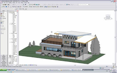
(Ensure your building is oriented correctly)
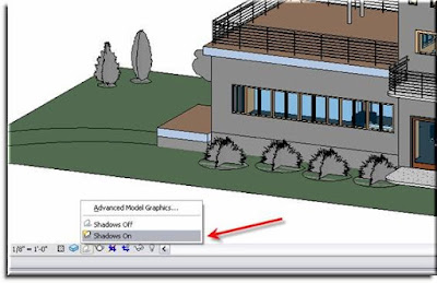
Next, turn your shadows [ON] at the Visual Graphics Control Bar:When you do this you will automatically notice that your building has an accurate representation of where the sun is in the sky and the model reflects this. While this is helpful, it currently doesn’t tell us
1.) Where we are
2.) What time of year it is
3.) What time of day it is
This of course is easily rectified. Once again go to down the Shadows Toggle button and Choose “Advanced Model Graphics”. You will get a dialogue box like the one below. Here adjustments can be made to the basic visual settings of how your shadows are displayed in the current 3D view. (Keep in mind that enabling shadows does NOT change this setting globally.)
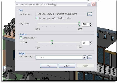
By default your Shadow Display will be set to something Generic like “Sunlight from Top Right”. To designate a specific city or indicate geographic coordinates select the small radio button next to Sun Position parameter "...".
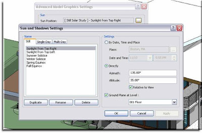
You should then see the “Sun and Shadows Settings” dialogue box. On the left side you have 3 tabs that give you the option to create one of three types of solar studies.
1.) Still: a single glimpse of your model at a certain time, day, and place/sun angle.
2.) Single-Day: An animated study of the suns travel across the sky on a given date, in a particular location
3.) Multi-Day: An animated study of the suns path at a specific time of day in a specific location over a designated period of time.
On the right side your options will change dependent upon which type of Solar Study you would like to create. For this example we’ll do a Single-Day study of this home on May 4th, 2009, if it was built in Albuquerque, New Mexico.
1.) Select the Single-Day tab
2.) Choose Duplicate
3.) Name new study: May 4th, 2009 – Albuquerque, NM, USA
4.) Select OK
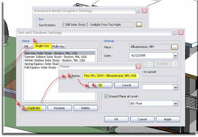
The new location will then be added to your list of single day locations. From here you will need to change the Place, Date, Time Range, and Interval which can be adjusted on the right portion of the dialogue box. (*The “Place” parameter does not automatically update when you create a new location. Be sure to make sure your selected location corresponds with your Place parameter before going forward.)
Selecting a Place is self explanatory though within this dialogue box it gives you the option to enter Lat. and Long. coordinates.
Now once everything is set up to you specifications, choose Apply and OK.
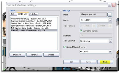
This will bring you back to your Advanced Model Graphics dialogue where you can make any additional adjustments to your visual appearance. Apply these and press OK. (*A benefit of the Apply button, as in Windows, makes the changes but, doesn’t shut the dialogue box so if you don’t like the way it looks you can change it again without having to recall the previous dialogue.)
You may notice a slight shift in what the drawing looks like depending upon how much you adjusted the contrast or brightness.
Now, in order to see this you solar study it is as simple as returning back to the Shadow Toggle button. Here you will find a new option that says, “Preview Solar Study”. Select this and you will notice a new options bar tool.

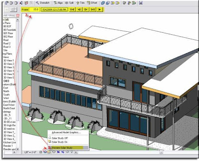
You will notice that this new options bar looks a lot like a Start, Stop, Play interface and that is essentially what it is. Here you can play the Solar Study, cycle through frame by frame, or skip from start to finish. The box next to the frame box displays the current settings and that you currently see on screen.
Go ahead and press play to see the results of your work!
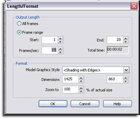
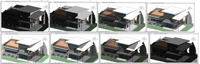
Once you have gotten your Study to look as you wish you can export it as an .avi file. Simply go to File>Export>Animated Solar Study and adjust the settings to reflect the Length, Size, and Style of the .avi.
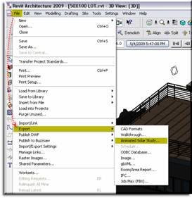
>>
Designate a location that you will remember and let Revit do its thing. The .avi will appear where ever you said for it to be saved and you can open it after it renders the animation.

- Daniel Childs
Ideate Inc