March 31, 2016

Revit Architecture: Manage Material Image Sample Size

Here's another question from one of my classes: “I have similar tiles in my project, but not 6”x6” as in the delivered material. How can I change the size?” 

You do not need to scan materials or take photographs and save images for materials, unless they are different from the image files in the Mat folder and you want to make a new material. You are provided many images and you can alter their sizes for a material. The same image can even be used at different sizes. The examples below are for a curtain material.

Example of 6"x6" small tartan
The rendering above shows the tartan material with a sample size matching the real life dimensions of the image file.

The rendering below shows the tartan material with a sample size adjusted to 36"x36".

Example of 3'x3' large tartan
Watch this video and master managing material image sample sizes. 

Thank you for reading. For more information on Revit and other Autodesk products, and information on training and consulting for the various products Ideate services, visit our website.


AEC Senior Application Specialist
Jim Cowan’s extensive AEC design industry experience, Autodesk design solutions expertise and status as an Autodesk Certified Instructor have made him a sought after University Curriculum developer, instructor and presenter. Jim’s areas of expertise include eLearning, interoperability between solutions and overcoming barriers to the adoption of Building Information Modeling (BIM). Educated in Architecture at Edinburgh College of Art/Heriot–Watt University and in Landscape Architecture at the University of Manitoba, Jim has a special focus on sustainability issues: daylight analysis, sun studies, lighting analysis, modeling buildings and conceptual energy modeling (models with shading devices). You can learn more from Jim on his YouTube Channel.

March 29, 2016

AutoCAD 2017 Hotfix 1

Here at Ideate, we pride ourselves on being proactive in keeping our customers informed of Autodesk product service packs and hotfixes. Yesterday, the Autodesk AutoCAD Product Team released Hotfix 1 for AutoCAD 2017. Per the Readme file, Hotfix 1 addresses the following issues:

• Layers of Xrefs that are frozen in viewports are plotting ellipses.
• In some languages the model documentation commands are not working.
• The number of hits for GetLineContainment is incorrectly counted.
• Xrefs show as needing reloading when opened from a network path to a  
shared folder.

The easiest way for you to download and install Hotfix 1 is via the new Autodesk Desktop App. If the new Autodesk Desktop App didn’t display a notification in your system tray, go to the Windows start button→All Programs→Autodesk→Autodesk Desktop App.


The Autodesk Desktop App replaces the older Autodesk Application Manager upon installing AutoCAD 2017. It is subscription aware and notifies you of service packs, updates, hotfixes, extensions, and learning content for your installed 2015-2017 products. You can categorize your updates for each product by selecting the product icon on the left Navigation Bar. Unfortunately, unlike the old Application Manager, you’re currently unable to tell the App to ignore undesired extensions.

Thank you for reading. For more information on other Autodesk products, and information on training and consulting for the various products Ideate services, visit our website at www.ideateinc.com.


ENI Application Specialist 
Daniel is an Application Specialist for Infrastructure Solutions at the Ideate Sacramento office. He is a California licensed Civil Engineer and LSIT with over 9 years land development design experience and 7 years Civil–GIS software consulting. Additionally, he provided 6 years of engineering support at a municipal public works department. At Ideate, Daniel assists Civil Engineering and Surveying firms in maximizing their utilization of AutoCAD Civil 3D through consulting, training, mentoring, and technical support. He conducts standard classroom and custom training on AutoCAD, Map 3D, and Civil 3D.

Interoperability: Manage Linked Content

This blog post is the result of a question asked by a contractor who wanted to maintain links to many different types of content, such as equipment specifications and documents. Their goal was to deliver a complete package, including this linked content, to a client so the virtual building could be managed after construction.

The example I am providing here is a modified scenario, explaining a historic building using multiple content links created within Revit families. Schedules in Revit or Ideate BIMLink with external spreadsheets can be used to manage the links. It is not difficult to come up with your own scenario where linked content lends itself to both a better understanding of a building proposal and management of the building.


The URL links can be made within existing families, say furniture with links to content, or can be custom-made for presentation purposes.
You can author the URL link in Revit, link the Revit file into 3D Studio Max, Showcase or Navisworks, to create deliverables such as rendered images or animations, and link the Revit file with its URL links to Navisworks for easy sharing, using a secure and free viewer. Note that the content is not embedded in Navisworks so the content folder also has to be available.


To get started with creating your own linked content in Revit, watch this video.

For more information on training and consulting for the various products Ideate services visit our website. Don't forget to keep an eye on our blog for continued solutions.


AEC Senior Application Specialist
Jim Cowan’s extensive AEC design industry experience, Autodesk design solutions expertise and status as an Autodesk Certified Instructor have made him a sought after University Curriculum developer, instructor and presenter. Jim’s areas of expertise include eLearning, interoperability between solutions and overcoming barriers to the adoption of Building Information Modeling (BIM). Educated in Architecture at Edinburgh College of Art/Heriot–Watt University and in Landscape Architecture at the University of Manitoba, Jim has special focus on sustainability issues: daylight analysis, sun studies, lighting analysis, modeling buildings and conceptual energy modeling (models with shading devices). You can learn more from Jim on his YouTube Channel.

March 28, 2016

e-Learning - Upcoming Infrastructure, Revit, and Ideate Software Classes

Join the Ideate Tech Experts for eLearning – live online classes that provide your entire organization with easy access to premium education.
3.29:Revit 201:
Getting Started with Roof Framing in Revit
4.1::Revit 201:
Revit MEP and Low Voltage Systems
4.7::Ideate Software:
Introduction to
Ideate Sticky
4.8::Infrastructure 201:
Data Shortcuts
4.13::Ideate Software:
Auditing Your Revit Project with Ideate Explorer
4.14::Revit 201:
Making Titleblocks and Drawing Lists
4.15::Navisworks 201:
Clash Detection
4.21::Ideate Software:
Revit Model Management with Ideate BIMLink
4.28::Ideate Software:
Ideate BIMLink for Revit MEP Projects
Each class is designed to give you specific, improved results in a particular topic. You can interact with the instructor right from your own office, while eliminating travel time. Because the class schedule rotates, you can easily select your topics of interest and choose the day which best meets your schedule.

Click here for class descriptions, times and registration link. Questions? Contact education@ideateinc.com

Get It. Know It. Use It.

Classroom Training - Open Revit, AutoCAD and Civil 3D Classes

Know It. Ideate Training.

Position yourself to land dream projects. Tap the full potential of your software solutions. Increase your facility, fluidity and capability to maximize the value of your precision software tools.
3.31-4.1::San Francisco
Revit Architecture Beyond the Basics
4.6-4.7::Portland
Revit Architecture Beyond the Basics
4.12-4.14::San Jose
AutoCAD Fundamentals
4.12-4.14::San Francisco
Revit Structure Fundamentals
4.12-4.14::Sacramento
Civil 3D Fundamentals
4.14::Seattle
Revit Architecture Families
Know your software. Sign up now! 

Contact the Ideate Training Department at 888.662.7238 x1012 or education@ideateinc.com

March 24, 2016

Revit MEP: Reference Planes for Lighting

Here at Ideate we get a lot of questions on issues that arise in the workplace. Our topic de jour came up because ceiling hosted lights are deleted when a ceiling is deleted – meaning they would need to be placed again. Or, maybe no ceiling host object is available for a light, perhaps because a ceiling component is a face-based generic model, such as a specific custom tile. Other options would be to use a generic ceiling (zero thickness) or an in-place ceiling family. This option which originated in Revit MEP may be especially useful where models are linked. For example, linking an architectural model to a lighting model.

In this example you see how to draft and name the reference plane, and then place lights. Now, you'll be able to move the lights when needed and not worry about a hosting ceiling being deleted and remodeled with subsequent loss of attachments.


 Lights with light source
Backlit ceiling
Get started by watching my video Revit MEP: Reference Planes for Lighting.

For more information on training and consulting for the various products Ideate services visit our website. Don't forget to keep an eye on our blog for continued solutions.


AEC Senior Application Specialist
Jim Cowan’s extensive AEC design industry experience, Autodesk design solutions expertise and status as an Autodesk Certified Instructor have made him a sought after University Curriculum developer, instructor and presenter. Jim’s areas of expertise include eLearning, interoperability between solutions and overcoming barriers to the adoption of Building Information Modeling (BIM). Educated in Architecture at Edinburgh College of Art/Heriot–Watt University and in Landscape Architecture at the University of Manitoba, Jim has special focus on sustainability issues: daylight analysis, sun studies, lighting analysis, modeling buildings and conceptual energy modeling (models with shading devices). You can learn more from Jim on his YouTube Channel.

March 23, 2016

Ideate, Inc. Recognized for Outstanding Achievement by Autodesk

Ideate was named the Autodesk North American Channel Marketing Partner of the Year for FY16. 

Qatanna Palioca, director of marketing for Ideate, Inc., accepted the award at a celebration at the Autodesk One Team Conference in Las Vegas on February 29, 2016. “I was honored to receive this award on behalf of the Ideate marketing team and our entire company,” said Qatanna. “We are all dedicated to promoting Autodesk products and the Ideate premium services, activities, and resources that support those products. It is thrilling to be recognized for our success.”

“Ideate has been a proud Autodesk reseller since 1992,” said Bob Palioca, president of Ideate, Inc. “We deeply value our relationship and appreciate the opportunity to partner with Autodesk to deliver outstanding solutions to our customers.”

“Autodesk is pleased to honor our top channel partners each year,” said Steve Blum, vice president of Worldwide Sales and Services, Autodesk. “Ideate shows its strong commitment to helping AEC companies across North America understand and benefit from the power of Autodesk software.” 


For more information, contact Qatanna Palioca, director of marketing, at qatanna.palioca@ideateinc.com.

March 22, 2016

Revit Architecture: This File Cannot Be Opened - Too Many Missing Elements

We have seen several cases in which customers have had issues opening their Revit files due to missing elements. While attempting to open their file, they receive the following message:

“The file .rvt cannot be opened. There are too many elements missing in it. Please contact Autodesk Support.”

 Possible Causes:
  1. There may be an issue with a file that is linked into the project you are attempting to open. For example, if the linked file has many missing elements and the link cannot be loaded, Revit may throw the missing elements warning.
  2. It’s possible the file had a problem reading the code to each element in the project. This tends to happen when one or more of the computers in the team is missing an update for Revit, whether they are working on the First Customer Ship (FCS) version, or any of the Updated Versions for Revit. What could happen is if someone saved the Revit file using a newer build of the software, the older version could have issues reading some of the elements within the file, since there is a possibility the newer build changes the way Revit reads a project file. When we are on tech support, we frequently look at the customer’s system to see which build of Revit they are currently using and then ask them to compare that build with others in the office. More times than not, we discover users are all over the place with their builds.
Possible Solutions:

  1. With an error like this, it is a good idea to try and audit the file to see if Revit can repair the file first. Chances are slim it will resolve the issue, but auditing is always a good starting point.
  2. Check to see if there is a missing linked file. If many elements are attached to a link and the link cannot be resolved, there could be a large number of "missing" elements (Autodesk website).
  3. If all the links are loaded without errors, check whether you can recover a backup of the project from before this error occurred. If successful, make sure to audit the recovered project (Autodesk website). It is important to ensure that you have a robust backup system for your Revit files. For example, ensure your office has a general file backup system. Also, make sure you have at least a few backups of your Central files, as well. Lastly, Local files can be used to create new Central files, especially in times of Central file corruption. Ensure users keep a few backups of their local files and remember, ALWAYS create new locals on a daily basis!
  4. Verify everyone on the team, or better yet, the entire office, is using the same build of Revit. For example, if one person is using Revit 2015 UR11 (First Customer Shipping version with Update Release 11) and the other is using Revit 2015 R2 UR12 (Second customer shipping version with Update Release 12), you are not on the same build. It is highly recommended everyone update to the latest build to help rule out file instability. Keep in mind, if you already have the file error and then you update everyone on the latest build, Revit will probably not resolve the missing elements issue, but it may reduce the chance of happening again since everyone is now on the same build.
  5. If at all possible, you can attempt to upgrade the project to the next release of Revit. For example, if the project was created in Revit 2015, try to see if you can Audit and Upgrade the file to Revit 2016 (remember, make sure everyone is on the same build of Revit). Keep in mind if this is successful and you wish to proceed using the new version of the software, the entire project team must also upgrade their Revit files, as well, since Revit files are NOT backwards compatible. 
Additional Resources to Review:

General Data Corruption

Revit Build Numbers

Recover a Workshared Central File


For more information on training and consulting for the various products Ideate services, visit our website.

Sash Kazeminejad
AEC Senior Application Specialist 
Sash brings proficiency in Autodesk solutions including AutoCAD and Revit Architecture to Ideate customers. His industry experience includes project management, BIM Management, and design for Architectural firms in California, Montana and Oregon. He is LEED accredited professional and is on track to achieve California licensure with Oregon to follow. In his academic life, Sash was awarded a variety of college scholarships, earned a BA in Environmental Design, a MA in Architecture from Montana State University (MSU) and taught Building Information Modeling courses at MSU Gallatin College. As a Revit Architecture Autodesk Certified Instructor, Sash provides Revit Architecture training and support for AEC firms. Find him on twitter.

March 21, 2016

Classroom Training - Open AutoCAD and Revit Classes

Know It. Ideate Training.

Position yourself to land dream projects. Tap the full potential of your software solutions. Increase your facility, fluidity and capability to maximize the value of your precision software tools.
3.29-3.31::Seattle
Civil 3D Fundamentals
3.31-4.1::San Francisco
Revit Architecture Beyond the Basics
4.6-4.7::Portland
Revit Architecture Beyond the Basics
4.12-4.14::San Jose
AutoCAD Fundamentals
4.12-4.14::San Francisco
Revit Structure Fundamentals
4.12-4.14::Sacramento
Civil 3D Fundamentals
Know your software. Sign up now! 

Contact the Ideate Training Department at 888.662.7238 x1012 or education@ideateinc.com

March 18, 2016

Generate Terrain Surfaces from Point Clouds in InfraWorks 360

If you have been using InfraWorks 360, you may have noticed that updates and version upgrades are released intermittently throughout the year, as opposed to on an annual basis like other Autodesk applications. The InfraWorks team is constantly working on new features and enhancements and the rolling upgrades allow users to gain access to new tools as soon as they are ready for release.

A recent update was posted in February, and it contains some great new enhanced tools. One in particular is the new preview feature for Point Cloud Terrain Generation. With this new enhancement to point cloud objects in InfraWorks 360, you can take a point cloud data source in the model and automatically generate a terrain surface from the data.

The icon is available under the InfraWorks persona, Analyze group and looks like a mountain with a dotted cloud shape (point cloud!) above it.

In order to use the command, you must first have a point cloud attached as a data source. After clicking the icon, a palette will appear with options for data source (which point cloud), ground and vertical feature recognition, and processing. The options available for ground processing include Less Detail for flat surfaces, Optimum (default) for normal surfaces and More Detail for surfaces that require higher detail or have more features that need to be modeled. Vertical Feature processing options include Fewer Features, Optimum (default) and More Features depending on what level of detail you need for non-ground features in the point cloud. 
After specifying your preferences, click Start Processing in the bottom right and InfraWorks 360 will do the rest. When processing is complete a new terrain object will appear in the model. It will appear as a grey generic terrain object. At this point in the preview, terrain styles do not appear applicable to point cloud terrain objects, so it will maintain a clay-like appearance in the model.

In addition to being able to generate the terrain object from a point cloud, the new command also opens up more capabilities of working with point clouds in InfraWorks 360. Point cloud data sources were primarily for visual reference in the past, as they were not interactive in the model. They could be used for displaying an object, but shadows, lighting and interaction with other objects was not available. Now that we can create a terrain object, shadows, lighting, terrain statistics and grading can be done with data that originally came from a point cloud in InfraWorks 360 giving you access to more design options early on in the process.

For more information on new features added to the latest update of InfraWorks 360 (V. 16.4.76.0) check out this post on the Autodesk Knowledge Network.

To see the new Point Cloud Terrain generator in action, see this video on our YouTube channel.

If you’re an InfraWorks 360 user that has been looking for a reason to upgrade, or weren’t aware that an upgrade was released last month, I hope you have some new insight on tools and enhancements that help make the decision easier.

Thank you for reading. For more information on InfraWorks 360 and other Autodesk products, and information on training and consulting for the various products Ideate services, visit our website.


ENI Manager & Senior Application Specialist
Matt is an ENI Manager and Senior Application Specialist in Ideate, Inc.’s Seattle office. He has a B.S. in Mechanical Engineering and is a licensed Civil Engineer. Prior to joining Ideate, Matt worked as a civil engineer, using Civil 3D on a variety of projects including site development, roadway improvements and infrastructure design. With over 10 years of experience in the civil engineering industry, Matt now provides training, consulting, technical support, and implementation strategies for organizations transitioning to Civil 3D. Matt is an Autodesk Certified Instructor (ACI), as well as an Autodesk Certified BIM Specialist: Roads and Highway Solutions. Additionally, Matt is and Autodesk Certified Professional for AutoCAD, and AutoCAD Civil 3D. You can also find Matt on Twitter.

March 17, 2016

Revit Architecture: Creating Organic Roofs with the Extrusion and Vertical Opening Tools

Hi folks, IX here, one of the Senior Application Specialists here at Ideate, Inc.

In this post I’m going to show you how to create an organic roof with the Roof by Extrusion and Vertical Opening tools in Revit. I like to call this workflow in Revit the "cookie cutter roof technique," but I’m getting ahead of myself. Let’s start-off with a review of the Roof by Extrusion and Vertical Opening tools.

Roof by Extrusion:
This tool allows you to create a roof by extruding a profile you have sketched. When using this tool, Revit will first ask you to set a workplane to sketch on and the highest level in the project (I call this the NO build area). Once these two options have been defined Revit is ready for you to create your sketch profile line(s). Once this is done, Revit will extrude the profile line from the sketch plan to the to the far end of the building. Typical types of roofs using this tool are Gambrel, Vaulted and Pleated, among others.

Roof by Extrusion
Vertical Opening:
This tool lets you cut a vertical or perpendicular opening through a roof, floor or ceiling element. First, Revit will ask you to select the element you wish to cut an opening into, then will switch to sketch mode and allow you to create an enclosed sketch that will be used to create the opening through the selected element. For roofs this tool is used to create opening that the Dormer Opening, Shaft Opening or Skylight windows tools would not be used for.

Vertical Opening
Alright, now that that’s out of the way. On to what I call the "cookie cutter roof technique." I’m sure we have all either had, or at least seen, holiday cookies such as Christmas, St. Patrick, or Halloween cookies, right?

Tasty and Uniform
To make this type of cookies you start by making the dough, rolling it out and placing a cookie cutter on the dough to get the base of the cookie. I’m going use this simple technique-metaphor to create an organic roof in Revit using the Roof by Extrusion and Vertical Opening tools.

Step 1: Creating a Roof Using the Roof by Extrusion Tool
  1. Start in the Default 3D View.
  2. Select the Roof by Extrusion button under the Architecture tab → Building panel → Roof button → Roof by Extrusion.
  3. Select the Pick a Plane option and hit the OK button.
  4. Select on a face that you’d like to sketch your profile on (in this case a wall).
  5. Set the Roof Reference Level and Offset (Level = level 2 and Offset = 20’-0”).
  6. Switch to the appropriate elevation view, in this case east elevation.
  7. Sketch out your desired profile.
  8. Select the green check from the Mode Panel on the Ribbon, when done.
Creating a roof using Roof by Extrusion
Step 2: Preparing the Roof Element for the Dough and Cookie Cutter
  1. Switch back to the Default 3D View.
  2. Select the top of the Cube to view the model in 3D, from the top.
  3. Select the Roof and Grip Arrows and stretch the roof out passed your desired overhang.
Preparing the Roof
Step 3: Making the Dough and Cookie Cutter Using the Vertical Opening Tool
  1. Switch to your Roof Plan View and select the Roof.
  2. Select the Vertical Opening tool from the Opening panel on the Ribbon.
  3. Change the Visual Style to Wireframe, if needed.
  4. Select the Rectangle tool from the Draw Panel.
  5. Create a sketch rectangle that falls outside the of roof element (This is your cookie dough!).
  6. Use the Draw tools from the Ribbon to create your desired shape of roof (This is the cookie cutter).
  7. Select the green check from the Mode Panel on the Ribbon when finished with your cookie cutter sketch.
  8. And there is your Organic Roof!
  9. To put the final touches on, you can select all the exterior Walls and use the “Attach Top/Base” tool to attach your exterior walls to the roof.
Creating a Vertical Opening
Check out this short video on the steps outlined above and give it a go. 

Enjoy my recommended workflow tips and tricks and have a happy St. Patrick’s Day!

Cheers,
IX

For more information on training and consulting for the various products Ideate services, visit our website.

Eugene O'Day, IX
AEC Senior Application Specialist
Eugene A. O’Day, IX, with more than 25 years of architectural and mechanical experience, offers a trained focus on all things Revit and BIM. Teaching is a passion of his. Eugene has been an instructor in undergraduate degree programs, has traveled worldwide teaching Autodesk solutions to major corporations, has taught at accredited ATCs throughout the Northwestern region, and is a frequent and popular instructor, speaker, and presenter for AUGI® CAD Camps, Revit – and related product user groups. He has also been a trusted public school district advisor on new drafting instructor hires. At Ideate, Eugene provides training and support for Revit Architecture, Revit Structure and AutoCAD. Eugene is also a Revit Architecture Autodesk Certified Professional.

March 15, 2016

New Director of Marketing to Lead Client-Focused Activities

Ideate, Inc. is pleased to announce that Qatanna Palioca has been named Director of Marketing. Qatanna joined Ideate four years ago, and she has been instrumental in developing innovative marketing campaigns that highlight the unique value that Ideate provides. As Director of Marketing, she will play a significant role in helping Ideate achieve its goals of delivering thought leadership presentations, developing the Revit community, and informing clients of industry trends and activities. 

Director of Marketing - Qatanna Palioca
In addition to leading the marketing activities of Ideate, Inc., Qatanna will oversee all marketing activities of Ideate Software, which develops Autodesk Revit add-on solutions that enable Revit users to save time, increase accuracy, improve project deliverables, and elevate design.

You can reach Qatanna at qatanna.palioca@ideateinc.com.

March 14, 2016

e-Learning - Upcoming Infrastructure, Revit, and Ideate Software Classes

Join the Ideate Tech Experts for eLearning – live online classes that provide your entire organization with easy access to premium education.
3.22:Revit 201:
Phasing A-Z
3.23::Ideate Software:
Revit Model Management with
Ideate BIMLink
3.24::Ideate Software:
Auditing Your Revit Project with Ideate Explorer
3.25::Infrastructure 201:
Intersection Design Tool
3.29::Revit 201:
Getting Started with Roof Framing in Revit Structure
4.1::Revit 201:
Revit MEP and Low Voltage Systems

4.7::Ideate Software:
Introduction to
Ideate Sticky
4.13::Ideate Software:
Auditing Your Revit Project with Ideate Explorer
Each class is designed to give you specific, improved results in a particular topic. You can interact with the instructor right from your own office, while eliminating travel time. Because the class schedule rotates, you can easily select your topics of interest and choose the day which best meets your schedule.

Click here for class descriptions, times and registration link. Questions? Contact education@ideateinc.com

Get It. Know It. Use It.

Classroom Training - Open Civil 3D, AutoCAD, Revit Architecture, and Revit Structure Classes

Know It. Ideate Training.

Position yourself to land dream projects. Tap the full potential of your software solutions. Increase your facility, fluidity and capability to maximize the value of your precision software tools.
3.29-3.31::Seattle
Civil 3D Fundamentals
3.31-4.1::San Francisco
Revit Architecture Beyond the Basics
4.6-4.7::Portland
Revit Architecture Beyond the Basics
4.12-4.14::San Jose
AutoCAD Fundamentals
4.12-4.14::San Francisco
Revit Structure Fundamentals
4.12-4.14::Sacramento
Civil 3D Fundamentals
Know your software. Sign up now! 

Contact the Ideate Training Department at 888.662.7238 x1012 or education@ideateinc.com

March 10, 2016

Revit Coordinate System: Project Base Point Versus Origin Point

I recently had the privilege of presenting at a few Revit User Groups in the Bay Area. The subject? The Revit Coordinate System! 

There is a lot of information out there on the Revit Coordinate System, but if you are not actively setting up models for coordination, it is easy to forget what it is about and how it works. Even sifting through the how-to’s can be quite complex. You really have to get your hands dirty and play around with the coordinate system in order to get a fundamental handle on how it works.

We will be publishing a series of blog posts that go through the Revit Coordinate System basics and tie everything together by assembling a workflow that satisfies most disciplines working together on a project.

To start things off, I figured it would be a good idea to chat about the Project Base Point versus the Origin Point. Why start here? Because when linking in files, we tend to pick the Origin to Origin option, hoping that models line up at the Project Base Point. But when they do not, we start questioning whether the models were properly set up to start with or whether we have an understanding of how the Revit Coordinate System actually works.

Dive-in now by watching
my first video on the topic, Revit 2016 Coordinate System: Project Base Point Versus Origin Point.

For more information on training and consulting for the various products Ideate services, visit our website.

Sash Kazeminejad
AEC Senior Application Specialist 
Sash brings proficiency in Autodesk solutions including AutoCAD and Revit Architecture to Ideate customers. His industry experience includes project management, BIM Management, and design for Architectural firms in California, Montana and Oregon. He is LEED accredited professional and is on track to achieve California licensure with Oregon to follow. In his academic life, Sash was awarded a variety of college scholarships, earned a BA in Environmental Design, a MA in Architecture from Montana State University (MSU) and taught Building Information Modeling courses at MSU Gallatin College. As a Revit Architecture Autodesk Certified Instructor, Sash provides Revit Architecture training and support for AEC firms. Find him on twitter. 

March 8, 2016

Autodesk Ideas Page

While on tech support at Ideate Inc., I often hear people articulating a new function or feature for an Autodesk product. These suggestions spawn from frustration and inspiration alike. They often come in the form of “I wish the software worked like this.” It turns out there is a place to voice these ideas. It is called the Ideas Page.

The Ideas Page is a part of the knowledge network and is a great place to communicate concerns as well as pitch ideas. If you have an idea, you can check out the site to see if it’s already been submitted. If it has, you can endorse the idea by liking it. The more endorsements an idea gets, the higher the likelihood it will be incorporated into a future release of the product. Occasionally, someone will comment on a post giving work-arounds for the current release.

Check out the Ideas Page. It is one of the ways Autodesk allows customers to give feedback. If you ever have an idea for a feature or function with in a program, I recommend posting it to the Autodesk Ideas Page.

For information on training and consulting for the various products Ideate services, visit our website. Also, check our blog for continued solutions as we encounter them.


Kate Ming
AEC Application Specialist
Kate is a California licensed civil engineer with a BS in Civil and Environmental Engineering from UC Berkeley. Prior to Ideate, she worked at a multinational company for four years doing general civil design on large infrastructure projects. She is versed in roadway, rail, utility design and site development. She also has experience with utility demand analysis and Low Impact Development plans. As a Civil 3D Autodesk Certified Professional Kate provides training and support for Civil 3D, AutoCAD, and InfraWorks.

March 7, 2016

Wrapping Your Head Around Wall Wraps

I was talking to Eugene O’Day, one of my Ideate colleagues and a contributor to the Ideate Solutions blog, regarding an issue he was running into with controlling the wrapping of wall layers at the insertion of a door or window within a wall. What he was looking for, was a way to control the distance a wall layer would wrap around the wall where a door or window was inserted.


Wall Wrap at Door/Window Insertion
By default, the System Family: Basic Wall allows you control how wall layers are wrapped around a wall where a door or a window have been inserted. The default option is Do not wrap. Options include: Do not wrap, Exterior, Interior, and Both.
Default Wall Wrapping at Inserts Options
When an option is chosen, the wall layers on that appropriate side, wrap around the wall and stop at the wall centerline. For example, if the Exterior option is chosen, all wall layers on the exterior side of the wall will wrap around the end of the wall and stop at the wall centerline.


Default Exterior Wall Wrapping Stops At Wall Centerline
The default options are great as a starting point, but if you would like to control the distance the exterior or interior wall layers’ wrap around the end of the wall, then you will need to modify the door or window family. Door and window families control the wall wrap of the wall they are inserted into.

When working with a door or window family, the simple use of reference planes and their “Wall Closure” parameter is used to control where the wall layers stop. If you need to control both the exterior side and the interior side wall wrap, draw two reference planes inside the wall found in the door and window family. Draw the reference planes across the door or window opening. Next select the reference planes and in the Properties Palette turn on the Wall Closure parameter. Additionally, consider naming the reference planes for future editing. I like to name my reference planes so that I can later come back and decipher what it was that I was doing. In this case, I named the exterior side reference plane “ Ext Wrap” and the interior side reference plane “Int Wrap” accordingly.


Create reference planes to represent where the wall layers will stop.
Assign each reference plane to the Wall Closure parameter.
Wherever you draw the reference plane(s), the wall layers will now stop at that point when a wall is set to wrap at the inserts. Should you wish to control the distance of the wall wraps from the edges of the wall, you will need to add parameters to make the reference planes parametric.

When adding dimensions to each wall closure reference plane, start the dimension from the outside edge of the wall, to the reference plane. This uses the outer edge of the wall as the controlling dimension edge and causes the reference plane to be adjusted when the dimension value is changed.
 
Dimension the location of the wall closure reference planes.
Select the outside edge of the wall first then the reference plane.

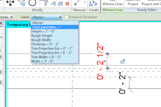
After the wall edges and wall closure reference planes have been dimensioned parameters can be assigned. Select one of the dimensions and in the Options bar select.

Select a dimension, go to the Label drop-down
and choose Add Parameter.
In the Parameter Properties dialog box, create a new parameter. In this example I have named the dimension controlling the exterior wrapping reference plane Exterior Wrap. Notice too that I have selected the Instance type of parameter. The reason I chose Instance was that I could use the same door type in a number of different wall types that had varying wall layer thicknesses. If a Type parameter is used, then different types of doors would be needed for the various types of wall the door family would be inserted into. Of course which parameter type you choose is up to you and your workflow.


Create a new parameter for the dimension.
Repeat the steps to create a parameter for the interior wall wrap dimension. Both wall closure reference planes have been dimensioned and parameterized.

Wall wrap parameters have been assigned.
After the door or window family has been created with the wall closure reference planes, dimensions and parameters, save the family. Load the family into the project.

In order to see your results, create a wall. Select the wall type and in the Properties Palette select the Edit Type button. In the Type Properties dialog box change the Wrapping at Inserts parameter to “Both.”


Change the Wrapping at Inserts parameter to “Both.”
Next, insert the door or window into the wall. If you had created the wall wrap parameters as an instance based parameter, in Properties, the parameters are available for you to control the distance the wall layer wrap
Enter the desired wall wrap distance.
If everything was done correctly, you should have a door or window family where you can control the wall layer wrap, providing a more accurate representation of the design intent. Unfortunately, this technique only applies to the wall wrap where door and window families have been inserted. 

Now that you have your head wrapped around wall wraps, go out and modify your door and window families. Until the next time, have fun with wall wrapping. 

If you would like to check these new features out or see what else is new in Revit 2016, take a look at my, and my colleagues videos on the Ideate, Inc. YouTube page.   

For more information on training and consulting for the various products Ideate services, visit our website at www.ideateinc.com


Ron Palma
AEC Application Specialist
Ron has over 24 years of experience in the architectural industry as a drafter, designer, lead project designer, trainer, and a CAD manager implementing Autodesk Architectural Solutions for a residential design firm. His instructional background includes being an Autodesk Certified Instructor (ACI), trainer, support technician, educator at Portland and Clackamas Community Colleges, as well as a U.S. Army certified instructor where he was a senior instructor at Ft Lewis Washington. Ron is a member of the Oregon Army National Guard, where he is a platoon sergeant specializing in training and mentoring soldiers in their careers. Ron is a published writer and continues to author professional technical training manuals and shorts for AutoCAD, AutoCAD Architecture, and Revit. As an Autodesk Certified Instructor and Revit Architecture Autodesk Certified Professional, Ron provides Revit Architecture and AutoCAD training and support for AEC firms. Find him on Twitter.