 |
|
Wall Wrap at Door/Window Insertion
|
 |
| Default Wall Wrapping at Inserts Options |
 |
| Default Exterior Wall Wrapping Stops At Wall Centerline |
When working with a door or window family, the simple use of reference planes and their “Wall Closure” parameter is used to control where the wall layers stop. If you need to control both the exterior side and the interior side wall wrap, draw two reference planes inside the wall found in the door and window family. Draw the reference planes across the door or window opening. Next select the reference planes and in the Properties Palette turn on the Wall Closure parameter. Additionally, consider naming the reference planes for future editing. I like to name my reference planes so that I can later come back and decipher what it was that I was doing. In this case, I named the exterior side reference plane “ Ext Wrap” and the interior side reference plane “Int Wrap” accordingly.
 |
| Create
reference planes to represent where the wall layers will stop. Assign each reference plane to the Wall Closure parameter. |
When adding dimensions to each wall closure reference plane, start the dimension from the outside edge of the wall, to the reference plane. This uses the outer edge of the wall as the controlling dimension edge and causes the reference plane to be adjusted when the dimension value is changed.
 |
| Dimension
the location of the wall closure reference planes. Select the outside edge of the wall first then the reference plane. |
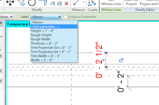
After the wall edges and wall closure reference planes have been dimensioned parameters can be assigned. Select one of the dimensions and in the Options bar select
 |
| Select
a dimension, go to the Label drop-down and choose Add Parameter. |
 |
|
Create a new parameter for the dimension.
|
 |
| Wall wrap parameters have been assigned. |
In order to see your results, create a wall. Select the wall type and in the Properties Palette select the Edit Type button. In the Type Properties dialog box change the Wrapping at Inserts parameter to “Both.”
 |
|
Change the Wrapping at Inserts parameter to “Both.”
|
 |
| Enter the desired wall wrap distance. |
For more information on training and consulting for the various products Ideate services, visit our website at www.ideateinc.com

Ron Palma
AEC Application Specialist
Ron has over 24 years of experience in the architectural industry as a drafter, designer, lead project designer, trainer, and a CAD manager implementing Autodesk Architectural Solutions for a residential design firm. His instructional background includes being an Autodesk Certified Instructor (ACI), trainer, support technician, educator at Portland and Clackamas Community Colleges, as well as a U.S. Army certified instructor where he was a senior instructor at Ft Lewis Washington. Ron is a member of the Oregon Army National Guard, where he is a platoon sergeant specializing in training and mentoring soldiers in their careers. Ron is a published writer and continues to author professional technical training manuals and shorts for AutoCAD, AutoCAD Architecture, and Revit. As an Autodesk Certified Instructor and Revit Architecture Autodesk Certified Professional, Ron provides Revit Architecture and AutoCAD training and support for AEC firms. Find him on Twitter.
