Hello, folks,
I wanted to report back after my last blog post, Ideate Announces Revit Architecture Fundamentals-Online.
We launched our Revit Architecture Fundamentals Online course on August 22nd, 2016, and I have to say, it has been a huge success! Students seem to really enjoy the format, and see value in Ideate, Inc. providing this online training option.
Today we are excited announce our next online offering: Revit Fundamentals for Interior Architecture – Online.
We have had many requests from our interior architecture clients asking us to teach a class geared towards their work and focus. Well, we listened and have created an online Revit class aimed at the interior architecture industry. Building on the success of the Revit Fundamentals online course, the Online Revit Fundamentals for Interior Architecture course will explore those fundamental parts of Revit that make the interior architecture industry a partner in the BIM world.
The online program:
How will the online training work? Class agendas will mirror our in house training by introducing the topic with a presentation, followed by a hands-on demonstration of the topic or function, where students follow along with the instructor, and a quick assessment of what was learned. Each topic will be covered in approximately 20-25 minutes, allowing you, the student, to focus on the material being covered in smaller, "bite-sized" chunks.
The class will be taught across five days, with each day occupying a four-hour block of time, break included. This allows users to spend a half a day in training, and still have time to focus on their day-to-day routines.
Topics Will Include:
• BIM and Revit Overview
• Working with Linked Files
• As-built strategies and phasing
• Grids and Levels
• Working with Walls, Doors, Curtain Walls/Storefronts
• Generating Interior Elevations, Sections, and 3D Camera and Presentation views
• Creating Floors and Ceilings
• Employing Design Options
• Documenting the model
• Working with Schedules
• Assembling Sheets and Printing
• Overview of Worksharing
Looking Forward:
Our inaugural Revit Fundamentals for Interior Architecture online class is scheduled for November of this year, beginning Monday, November 28, 2016 and concluding Friday, December 2, 2016. Future online classes will be released over the following months and will include topics such as Revit Families, Revit MEP Beyond the Basics, and Revit for Landscape Architecture.
I look forward to helping you continue your education, and providing this next online training opportunity from Ideate, Inc.
Take Care Until Next Time,
Ron
For more information on the software solutions, training and consulting Ideate provides, please visit the Ideate Inc. website.
Ron Palma
AEC Application Specialist
Ron has 25+ years of experience in the architectural industry as a drafter, designer, lead project designer, trainer, and a CAD manager implementing Autodesk Architectural Solutions for residential design firms. His instructional accomplishments include: Autodesk Certified Instructor (ACI), trainer, support technician, educator at Portland and Clackamas Community Colleges, as well as a U.S. Army certified instructor. Ron holds a BA in Instructional Design suma cum laude, is a member of the Oregon Army National Guard, where he is a First Sergeant of an Infantry Company, specializing in training and mentoring soldiers in their careers, and has been deployed to Afghanistan in support of Operation Enduring Freedom and Operation Resolute Support. Ron is a published author and continues to write professional technical training manuals and shorts for AutoCAD, AutoCAD Architecture, and Revit. As an Autodesk Certified Instructor and Revit Architecture Autodesk Certified Professional, Ron continues to provide Revit Architecture and AutoCAD training and support for various AEC firms. @RonPalmaAEC
September 29, 2016
September 27, 2016
Export a Bridge Model from InfraWorks 360 to Revit with One Click
Ok, I lied – it is three clicks: left click – right click – left click.
But seriously, it is that easy with the release of InfraWorks 360 2017. We, at Ideate, are dedicated to highlighting and bringing these nifty new features to you, saving you time and research.
Alright, jumping in; if you conceptualize a bridge using the bridge design tool in InfraWorks 360, you can take it to Revit for structural detailing, analysis, rebar layout, documentation and construction.
One, left click on the bridge model in InfraWorks, let’s say on a pier or its cap.
Two, right click.
Three, left click, select "Send to Revit."
The command will start cranking and building the model in Revit.
It will build the Revit families and generate the model without any user input.
Then, Voila!, it opens the model in Revit!
You are now free to continue with detailed design and analysis using Revit, and it all started with a conceptual bridge design in InfraWorks 360.
If you want to learn more about InfraWorks, start by signing up for our Intro to InfraWorks online e201 and one of Ideate's experts will guide you through the basics so you don’t have to dig in on your own.
For more information on the software solutions, training and consulting Ideate provides, please visit the Ideate Inc. website.
Senior Application Specialist Infrastructure
Gaurav is a Senior Application Specialist for Infrastructure Solutions at Ideate based out of San Francisco. He has over 18 years of experience in construction and related software industry. With this extensive design technology background he helps engineering and surveying companies, federal and state government agencies, and ENR 500 firms critically analyze and improve their construction drawing production process. He implements Civil infrastructure design technology led by InfraWorks and Civil 3D and has helped Ideate grow Civil Infrastructure Services. Being an industry recognized speaker he has presented cutting edge design technology at several industry conferences such as Autodesk University. Find Gaurav on Twitter.
September 22, 2016
Ideate Sponsors Leap's 34th Annual Sandcastle Classic
As architects, engineers, and designers, we are thrilled to once again sponsor Leap’s Annual Sandcastle Classic.
This fun and educational event challenges Bay Area architects, designers, contractors, engineers, companies, and elementary school students to work together. They design, model, and create larger than life and truly stunning sand sculptures – from alien beings, mermaids, and other mythical creatures to abstract structures and traditional sandcastles. Awards will be presented in several categories, including Best in Show, Best Participation of Students, Best Site Sign, Best Team T-Shirt, People’s Choice Award, and Top Fundraising Team.
In addition to presenting a great learning opportunity for adults and kids alike, the Sandcastle Classic raises money for Leap, a Bay Area organization that works to make art a fundamental part of every child’s education. Last year’s event raised more than $262,000, making it Northern California’s largest sandcastle competition. Leap used these funds to provide art experiences and learning to more than 6,000 students in 25 schools over the course of the past year.
Ideate first jumped on board as a sponsor in 2009 and hasn’t looked back. We are excited to be a part of a fundraiser that provides enormous benefit to our schools while introducing young people to the fields we are so passionate about.
This year’s event, which is free, will be held on October 15, 2016 from 11:00 AM to 4:00 PM on Ocean Beach near the intersection of Balboa Street and the Great highway. In addition to sandcastles, attendees will enjoy raffles, food trucks, and with luck, beautiful San Francisco weather.
For more information about the event, including details on how to get involved, visit the Sandcastle Classic website.
September 20, 2016
AutoCAD Advanced Online Training from Ideate, Inc.
Are you a CAD drafter or designer going beyond the fundamental commands in AutoCAD? Are you a CAD manager or power user in charge of creating custom styles and blocks or sheet sets to improve your organizations production efficiency? If so, our new AutoCAD Advanced online course is right for you.
Here at Ideate, we’ve been working hard to develop new training offerings that make it easier and more convenient for our customers to get the training they need. Our first new class to be released for AutoCAD users will be the AutoCAD Advanced online course.
The AutoCAD Advanced online course will be presented in two (4-hour) virtual sessions focusing on advanced CAD user and CAD manager commands and functionality. Although this class will be presented online, it will still be a live, instructor-led course with handouts and exercises. Sessions will be scheduled on back to back days so attendees can participate in training without having to travel or be out of the office for multiple days in a row.
Day 1 of the AutoCAD Advanced online course will cover styles, text, tables, layer tools, eTransmit and hyperlinks. Day 2 will cover dynamic blocks, sheet sets, output and publishing. For a more detailed outline and to register for AutoCAD Advanced online training, visit the Ideate website.
Our first course is coming up soon on November 3rd and 4th. If you have any questions or need more information on Ideate’s training options, feel free to contact education@ideateinc.com
Hope to see you in November!
ENI Manager & Senior Application Specialist
Matt is an ENI Manager and Senior Application Specialist in Ideate, Inc.’s Seattle office. He has a B.S. in Mechanical Engineering and is a licensed Civil Engineer. Prior to joining Ideate, Matt worked as a civil engineer, using Civil 3D on a variety of projects including site development, roadway improvements and infrastructure design. With over 10 years of experience in the civil engineering industry, Matt now provides training, consulting, technical support, and implementation strategies for organizations transitioning to Civil 3D. Matt is an Autodesk Certified Instructor (ACI), as well as an Autodesk Certified BIM Specialist: Roads and Highway Solutions. Additionally, Matt is and Autodesk Certified Professional for AutoCAD, and AutoCAD Civil 3D. You can also find Matt on Twitter.
September 15, 2016
Revit 2017: Electrical Apparent Load Calculation Options
One of the new MEP design enhancements in Revit 2017 is the Electrical Apparent Load Calculation options to help better communicate the engineering data.
With the option to choose the default method, which is sum the true load and reactive load, or sum the apparent load which is a more simplified approach, you now have more control over the method you prefer to use to calculate the electrical loads with Apparent Load Calculation Options.
Here is a short video demonstrating how new electrical calculation options enable you to design more efficiently and choose the calculation options for your needs.
For more information on the software solutions, training and consulting Ideate provides, please visit the Ideate Inc. website.
Vasudha is an MEP Application Specialist at Ideate, Inc. based on San Francisco office. She has a Master’s degree in Energy Engineering from the University of Illinois at Chicago where she specialized in HVAC design, green buildings and energy analysis. Prior to Ideate, she interned at a few multinational companies where she performed finite element analysis for design validation of components. Vasudha provides Revit MEP training and support for various AEC firms.
September 13, 2016
Interoperability: Image Sequences for Easy Editing
Did you know can create and save a sequence of images from 3ds Max as a single file (AVI or MOV)?
By combining the best features from Revit and 3ds Max it is possible to edit specific frames (images) within a movie. From Revit we get the required, linked building elements with their materials, and from 3ds Max we get the ability to render a sequence of PNG files. This workflow saves us the trouble of having to re-rendering the whole movie, say after removing reflecting materials, or making other edits.
In this video tutorial, Interoperability: Image Sequencing for Easy Editing, only the first 40 images of a 900 image sequence needed to be fixed. The first sequence had a reflective paver material that took 40 minutes to render in one frame. The second, “fixed,” sequence used a matte material that took about 20 minutes to render in one frame.
The building used for this example is a proposed prefabricated house, designed by Lt. Russell M. Amdal and featured in Art and Architecture Case Studies, 1945.
For more information on the software solutions, training and consulting Ideate provides, please visit the Ideate Inc. website.
By combining the best features from Revit and 3ds Max it is possible to edit specific frames (images) within a movie. From Revit we get the required, linked building elements with their materials, and from 3ds Max we get the ability to render a sequence of PNG files. This workflow saves us the trouble of having to re-rendering the whole movie, say after removing reflecting materials, or making other edits.
In this video tutorial, Interoperability: Image Sequencing for Easy Editing, only the first 40 images of a 900 image sequence needed to be fixed. The first sequence had a reflective paver material that took 40 minutes to render in one frame. The second, “fixed,” sequence used a matte material that took about 20 minutes to render in one frame.
First Sequence with relective paver material |
Second, fixed, sequence with matte paver material |
For more information on the software solutions, training and consulting Ideate provides, please visit the Ideate Inc. website.
AEC Senior Application Specialist
Jim Cowan’s extensive AEC design industry experience, Autodesk design solutions expertise and status as an Autodesk Certified Instructor have made him a sought after University Curriculum developer, instructor and presenter. Jim’s areas of expertise include eLearning, interoperability between solutions and overcoming barriers to the adoption of Building Information Modeling (BIM). Educated in Architecture at Edinburgh College of Art/Heriot–Watt University and in Landscape Architecture at the University of Manitoba, Jim has a special focus on sustainability issues: daylight analysis, sun studies, lighting analysis, modeling buildings and conceptual energy modeling (models with shading devices). You can learn more from Jim on his YouTube Channel.
September 8, 2016
Where Are My Callout Tags?
One of the biggest issues us Revit users run into is, of course, missing elements.
I am sure each of you have scratched your head a time or two wondering where in the world certain items are. Specifically, when dealing with Callouts and Sections there is a parameter that controls which views those particular callouts will appear in, based on the scale of the view.
Callout Views
When you create a Callout View you have the option to create a parent view or a detail view. In the View Properties for the callout detail view you have a parameter called Show In. This parameter controls whether this callout shows in the parent view only, or in intersecting views, as well. (Please note this visibility option only applies to detail callout view and not floor plan callouts.)
When the Show In value is Parent View Only, Hide at Scales Coarser Than will be read-only. When the Show In value is Intersecting Views, you can change the value of the Hide at Scales Coarser Than parameter. As a result, Revit displays the callout tag in any view that intersects the parent view perpendicularly, as long as the view scale is more detailed than the scale specified by Hide at Scales Coarser Than.
Section Views
Section Views do not have the Show In parameter, however they do have Hide at Scales Coarser Than. The section instance parameter Hide at Scales Coarser Than establishes a scale at which sections are either shown or hidden in other views. For example, a section tag can be hidden at scales coarser than 1/4”=1’0”.
IdeateApps Xray
Another great tool if you are missing elements in your view is the new IdeateApps tool, Ideate XRay, it will find the hidden callouts and tell you exactly where and why they are hidden, including the parameters discussed above.
To learn more, and see these parameters in action, check out my video, Where Are All My Callout Tags?
Thank you for reading. For more information on the software solutions, training and consulting Ideate provides, please visit the Ideate Inc. website.
I am sure each of you have scratched your head a time or two wondering where in the world certain items are. Specifically, when dealing with Callouts and Sections there is a parameter that controls which views those particular callouts will appear in, based on the scale of the view.
Callout Views
When you create a Callout View you have the option to create a parent view or a detail view. In the View Properties for the callout detail view you have a parameter called Show In. This parameter controls whether this callout shows in the parent view only, or in intersecting views, as well. (Please note this visibility option only applies to detail callout view and not floor plan callouts.)
When the Show In value is Parent View Only, Hide at Scales Coarser Than will be read-only. When the Show In value is Intersecting Views, you can change the value of the Hide at Scales Coarser Than parameter. As a result, Revit displays the callout tag in any view that intersects the parent view perpendicularly, as long as the view scale is more detailed than the scale specified by Hide at Scales Coarser Than.
Section Views do not have the Show In parameter, however they do have Hide at Scales Coarser Than. The section instance parameter Hide at Scales Coarser Than establishes a scale at which sections are either shown or hidden in other views. For example, a section tag can be hidden at scales coarser than 1/4”=1’0”.
Another great tool if you are missing elements in your view is the new IdeateApps tool, Ideate XRay, it will find the hidden callouts and tell you exactly where and why they are hidden, including the parameters discussed above.
Download your free, fully functioning IdeateApps trial here. |
Thank you for reading. For more information on the software solutions, training and consulting Ideate provides, please visit the Ideate Inc. website.
AEC Application Specialist
Emily Clark holds a Bachelor of Architecture degree from Kansas State University, and has over 19 years of experience in the Architecture industry. Her experience includes working for a number of Architecture and Design/ Build firms in the Western United States. She has been a Project Designer, Intern Architect, BIM Manager and Design Technology Manager. She has contributed to the completion of projects ranging from high–end custom residential to Education and Healthcare design. She has worked with multiple platforms and her passion for BIM has enabled her to help transition firms and advance with technology. At Ideate, Emily provides training and support for Revit Architecture.
September 6, 2016
Interoperability: Animated 3d Studio Max AEC Objects and Revit Models
Only a camera can be animated within Revit, but we often need opening doors, windows or other animated objects in a presentation. This workflow shows how we can reuse our Revit model, minus doors, plants and people, and add animatable objects from 3d Studio Max. The model we will be using as an example is a prefabricated house as proposed by Lt. Russell M. Amdal, Art and Architecture Case Studies, 1945.
By combining the best features of both products we get, from Revit, the majority of the required building elements, and the AEC objects from within 3d Studio Max. We can use their parametric properties to animate them – such as the angled opening of the door.
This example shows a 3d Studio Max pivot door in the door opening that can be animated.
For a close-up look at this workflow, watch my video Interoperability: Animated 3d Studio Max AEC Objects and Revit Models.
Thank you for reading. For more information on the software solutions, training and consulting Ideate provides, please visit the Ideate Inc. website.
AEC Senior Application Specialist
Jim Cowan’s extensive AEC design industry experience, Autodesk design solutions expertise and status as an Autodesk Certified Instructor have made him a sought after University Curriculum developer, instructor and presenter. Jim’s areas of expertise include eLearning, interoperability between solutions and overcoming barriers to the adoption of Building Information Modeling (BIM). Educated in Architecture at Edinburgh College of Art/Heriot–Watt University and in Landscape Architecture at the University of Manitoba, Jim has a special focus on sustainability issues: daylight analysis, sun studies, lighting analysis, modeling buildings and conceptual energy modeling (models with shading devices). You can learn more from Jim on his YouTube Channel.
September 1, 2016
Revit 2017: Filling Gaps in a Revit Fabrication Model
Fabrication detailing in Revit 2017 supports different MEP detailing workflows. In this post, I'll provide a brief rundown for each.
For each fabrication model you must specify a fabrication configuration and load services. You can then place parts to create a detailed fabrication model in Revit, or convert an existing Revit model with generic duct, pipe, and electrical containment parts to a model that uses fabrication parts.
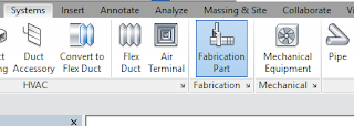
Continue to add fabrication parts and modify the elements in the model as needed. For all those new to the feature this can be found on the Systems tab > Fabrication Part:
Content:
Download sample fabrication configurations for use with the MEP features of Revit. The sample fabrication configurations contain generic US Imperial and UK Metric content.
Download the Imperial and Metric sample configurations
However, to access and use a full set of real-world content, I would suggest an installation of any of the Autodesk Fabrication products: Trim and Extend:
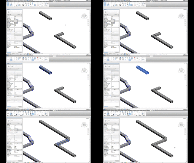
Use the Trim/Extend tool to fill a gap between two straights, For example, when connecting a duct branch to a main or pipework to a header:
Quick Connect:
Use the Quick Connect tool to fill a gap between a fitting and another straight where no additional fittings are needed.
Please note: the Quick Connect command is available only when a fitting is selected. The command is disabled when a straight is selected. You can use this tool to drag the connector onto another part to connect them:
Route & Fill:
Use the Route and Fill tool to add parts between two open connectors in a faster, more efficient way than placing parts one-by-one. The Route and Fill tool provides one or more solution depending on the service. You can narrow the number of solutions by filtering the fittings used, switch direction of the route, and even filter the solutions to force it to use certain parts:
Per the Autodesk help file, one thing to remember with this feature is that “A route must exist in a single plane. Solutions that require two planes or three bends are not supported.” This means varying height connections that also require bends will not automatically connect. It may be quicker using the “Design to Fabrication” feature for these situations.
Design to Fabrication:
Use the Design to Fabrication tool to convert a design model with Revit elements to a fabrication model with LOD 400 fabrication parts.
You can convert selected parts, or an entire duct or pipe network. The Design to Fabrication tools provide a more efficient workflow, since the fabrication model does not need to be redrawn from scratch. The result of the conversion is based on the design line algorithm used by the Autodesk Fabrication products, and uses the same content available in the Autodesk Fabrication products:
It's important to note, this is a one-way process; once the Revit MEP Design has been converted to Fabrication Parts, it cannot be reversed. I would suggest using a copy of the MEP Design to convert, as this gives us the benefit of linking the projects for comparison.
Swap Parts:
In 2017 we now have the ability to swap Fabrication parts in the same way as Revit Families:
Optimize Lengths:
This feature allows you to optimize the straight lengths of generic ductwork by adding, removing, or modifying lengths of straight segments.
Please Note: If a straight is pinned, or part of a group, it will not be optimized.
To go in-depth with each of these features, check out my videos in the Revit Architecture, Revit MEP and Revit Structure 2017 playlist on Ideate Inc.'s YouTube Chanel.
For each fabrication model you must specify a fabrication configuration and load services. You can then place parts to create a detailed fabrication model in Revit, or convert an existing Revit model with generic duct, pipe, and electrical containment parts to a model that uses fabrication parts.
Continue to add fabrication parts and modify the elements in the model as needed. For all those new to the feature this can be found on the Systems tab > Fabrication Part:
Content:
Download sample fabrication configurations for use with the MEP features of Revit. The sample fabrication configurations contain generic US Imperial and UK Metric content.
Download the Imperial and Metric sample configurations
- Click the file names: www.autodesk.com/revit-2017-mep-fab-sample-content-imperial and www.autodesk.com/revit-2017-mep-fab-sample-content-metric.
- Open the files. The files are installed to:
- C:/Users/Public/Documents/Autodesk/Fabrication
/Revit MEP Imperial Content/Vx.xx
- C:/Users/Public/Documents/Autodesk/Fabrication
/Revit MEP Metric Content/Vx.xx
Use the Trim/Extend tool to fill a gap between two straights, For example, when connecting a duct branch to a main or pipework to a header:
Use the Quick Connect tool to fill a gap between a fitting and another straight where no additional fittings are needed.
Use the Route and Fill tool to add parts between two open connectors in a faster, more efficient way than placing parts one-by-one. The Route and Fill tool provides one or more solution depending on the service. You can narrow the number of solutions by filtering the fittings used, switch direction of the route, and even filter the solutions to force it to use certain parts:
Design to Fabrication:
Use the Design to Fabrication tool to convert a design model with Revit elements to a fabrication model with LOD 400 fabrication parts.
You can convert selected parts, or an entire duct or pipe network. The Design to Fabrication tools provide a more efficient workflow, since the fabrication model does not need to be redrawn from scratch. The result of the conversion is based on the design line algorithm used by the Autodesk Fabrication products, and uses the same content available in the Autodesk Fabrication products:
Swap Parts:
In 2017 we now have the ability to swap Fabrication parts in the same way as Revit Families:
This feature allows you to optimize the straight lengths of generic ductwork by adding, removing, or modifying lengths of straight segments.
Please Note: If a straight is pinned, or part of a group, it will not be optimized.
To go in-depth with each of these features, check out my videos in the Revit Architecture, Revit MEP and Revit Structure 2017 playlist on Ideate Inc.'s YouTube Chanel.
Thank you for reading. For more information on the software solutions, training and consulting Ideate provides, please visit the Ideate Inc. website.
Senior Application Specialist MEP/AEC Solutions
Bill has over 25 years experience in applying MEP & AEC design solutions for large commercial companies, this has led to actively develop Autodesk® Revit® implementation strategies, techniques, and procedures for architectural and MEP companies. He has worked for TEECOM Design Group, GTE/GTEL, Greg LeDoux and Associates, and Scottish Power in England. Bill is an Autodesk MEP Implementation Certified Expert, and has been the Lead Designer for several multimillion dollar communication sites which have included structural, electrical, HVAC, conduit, cable plans and equipment layouts. He graduated from the Pasadena Institute of Technology and has a Sustainable Design Certification from the University of California at Berkeley.
Subscribe to:
Posts (Atom)