Showing posts with label William Johnson. Show all posts

November 10, 2016

Revit MEP: It’s shocking news - Electrical Circuit Schedule

Hello All, this post is to remind all the Revit MEP “Reviteers” out there that Revit is as much a documentation and database tool as it is a design assist tool. In this post, I will cover how you can use certain schedules to help make informed decisions about specific elements of design, such as voltage drop and wire sizing.

It’s important to note, Revit tends to overestimate the wire length at times, and therefore outputs a higher voltage drop than necessary. These are not intended to be exact numbers; they are intended to inform the designer when further research is needed. Also, note the Feeder Tag column (i.e., MCB2, MCA2) is not directly related to the wire size. There are still a few quirks in Revit that cause any Automated Feeder Tags/schedules to be unreliable in rare cases, and unfortunately unusable on most projects.


Now, let’s dive in.


First, create an Electrical Circuit schedule with the following Parameters and add a Calculated Value, Voltage Drop (%), with the formula shown. (click to enlarge images.)

The schedule below shows a portion of the resulting Electrical Circuit schedule. This information is directly related to the Panel Schedule, so all information can be updated in any of the three following places: floor plans, Panel Schedules, or the schedule below.
It’s also possible to apply conditional formatting to the schedule to highlight areas of concern. Below, the conditional formatting for the Voltage Drop (%) field is shown, which highlights any value over 3% with a red background. This is very helpful when trying to quickly identify problematic circuits needing more research.
As stated previously, these schedules can be used for design assist tasks. Take breaker sizing for example: adding the True Current field to the schedule will show the design load, or in some cases, one could use the value of Apparent Current. It’s easy to add a few simple Calculated Values and conditional formatting to quickly double-check that the size of the breaker is adequate for the load.

Of course, this will not be 100% accurate in all situations. Motors, for example, will need further engineering.

To check breaker size, first add the True Current, or Apparent Current, field to the schedule (not shown).

Then add the two following Calculated Values with the shown conditional formatting on the Current Difference:

125% True Current is the minimum allowed breaker size, and ensures that the circuit is never more than 80% loaded.

The current difference takes that minimum breaker size and subtracts the breaker rating.

With a value of zero, the breaker size = the minimum allowed, therefore the size is adequate. 

Any negative numbers are acceptable, as they indicate a breaker size larger than the minimum allowed. The conditional formatting, when this number is larger than zero, is highlighted in red to illustrate an inadequately sized breaker.

Now you're ready to get started using Revit for design assist tasks, try this workflow in action.


For more information on the software solutions, training, and consulting Ideate provides, please visit the Ideate Inc. website.

http://www.ideateinc.com/about/about.htmlBill Johnson
Senior Application Specialist MEP/AEC Solutions

Bill has over 25 years experience in applying MEP & AEC design solutions for large commercial companies, this has led to actively developed Autodesk® Revit® implementation strategies, techniques, and procedures for architectural and MEP companies. He has worked for TEECOM Design Group, GTE/GTEL, Greg LeDoux and Associates, and Scottish Power in England. Bill is an Autodesk MEP Implementation Certified Expert, and has been the Lead Designer for several multi-million dollar communication sites which have included structural, electrical, HVAC, conduit, cable plans and equipment layouts. He graduated from the Pasadena Institute of Technology and has a Sustainable Design Certification from the University of California at Berkeley.

November 1, 2016

Revit MEP Families – Diamonds in the Rough

I bet everyone asks the same question when they start to learn Revit: What is a Family?

When you start a new Revit file, you have the option to choose from Project, Family, Titleblock, or Annotation Symbol. It is easy to understand what Project, Titleblock, and Annotation Symbol are without further explanation. But what is a Family?

Families are the components you use to build your model, such as walls, windows, and doors. For the Mechanical, Electrical and Plumbing (MEP) disciplines, Families are items like Mechanical Equipment, Electrical Equipment, and Lighting Fixtures. Each Family can have multiple types of components comprised of differing sizes, materials, or parameter variables.

One of the many keys to mastering Autodesk Revit MEP software is the ability to create intelligent, parametric Families for your content libraries. It's not as easy as simply building a 3D model. Parameters, and the valuable data they contain, make up one of the more powerful functions at the core of Building Information Modeling (BIM), and Autodesk Revit-based software products. The information contained in parameters is of special interest to MEP engineers, and any user who learns how working with parameters in Revit MEP affects project workflow, construction documentation, and the transfer of valuable data.

Recently, we started to receive more requests for training specifically related to Revit MEP Families. With the expansion of our virtual training program, now is the perfect time for us to introduce a new course focusing on those Revit Families specific to MEP projects and designers.

Scheduled over two, four-hour virtual sessions, our Revit MEP Families class will show you how to use the modeling tools in the Revit Family Editor. You will learn the process of creating intelligent parameters to properly control family dimensions, behavior, and visibility. Additionally, we will teach you how to make sure your Families "play nice" with other elements in your model.

Learning Objectives

At the end of this class, you will be able to:

• Employ the modeling tools found in the Family Editor
• Determine the correct Family template on which to base custom content
• List various types of Revit parameters, and explain how they affect your documents, workflow, and time
• Use parameters in the Family, and Project environment
• Work with nested Families
• Apply Revit MEP Connectors and understand how data flows between elements
• Understand Lookup Tables, and how to use them in conjunction with Revit MEP families of certain categories

So, whether you are looking to create that amazing Family that behaves and prints exactly the way you want it to, or want to customize an existing Family to your project needs, mastering the art of the parametric Family is a huge productivity booster, and it’s a lot of fun, too!

Join us for our first Revit MEP Families class on November 21st-22nd. Class times, and additional registration details can be found on the Ideate, Inc. website.

http://www.ideateinc.com/about/about.htmlBill Johnson
Senior Application Specialist MEP/AEC Solutions

Bill has over 25 years experience in applying MEP & AEC design solutions for large commercial companies, this has led to actively developed Autodesk® Revit® implementation strategies, techniques, and procedures for architectural and MEP companies. He has worked for TEECOM Design Group, GTE/GTEL, Greg LeDoux and Associates, and Scottish Power in England. Bill is an Autodesk MEP Implementation Certified Expert, and has been the Lead Designer for several multimillion dollar communication sites, which have included structural, electrical, HVAC, conduit, cable plans, and equipment layouts. He graduated from the Pasadena Institute of Technology and has a Sustainable Design Certification from the University of California at Berkeley.


September 1, 2016

Revit 2017: Filling Gaps in a Revit Fabrication Model

Fabrication detailing in Revit 2017 supports different MEP detailing workflows. In this post, I'll provide a brief rundown for each.

For each fabrication model you must specify a fabrication configuration and load services. You can then place parts to create a detailed fabrication model in Revit, or convert an existing Revit model with generic duct, pipe, and electrical containment parts to a model that uses fabrication parts.

Continue to add fabrication parts and modify the elements in the model as needed. For all those new to the feature this can be found on the Systems tab > Fabrication Part:

Content: 

Download sample fabrication configurations for use with the MEP features of Revit. The sample fabrication configurations contain generic US Imperial and UK Metric content.

Download the Imperial and Metric sample configurations

  1. Click the file names: www.autodesk.com/revit-2017-mep-fab-sample-content-imperial and www.autodesk.com/revit-2017-mep-fab-sample-content-metric.
  2.  
  3. Open the files. The files are installed to:
  • C:/Users/Public/Documents/Autodesk/Fabrication /Revit MEP Imperial Content/Vx.xx
  • C:/Users/Public/Documents/Autodesk/Fabrication /Revit MEP Metric Content/Vx.xx
However, to access and use a full set of real-world content, I would suggest an installation of any of the Autodesk Fabrication products:
Trim and Extend:

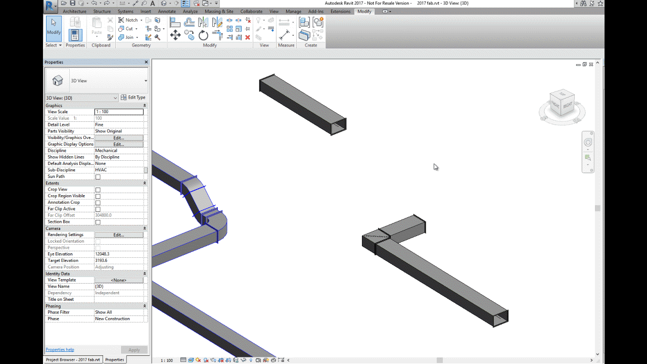
Use the Trim/Extend tool to fill a gap between two straights, For example, when connecting a duct branch to a main or pipework to a header:

Quick Connect:

Use the Quick Connect tool to fill a gap between a fitting and another straight where no additional fittings are needed. 


Please note: the Quick Connect command is available only when a fitting is selected. The command is disabled when a straight is selected. You can use this tool to drag the connector onto another part to connect them:
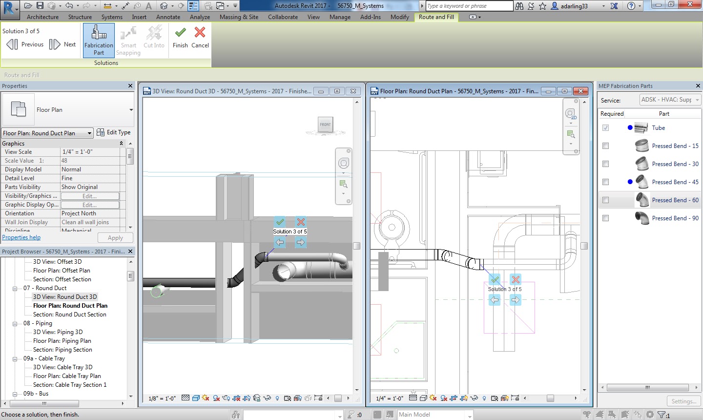
Route & Fill:

Use the Route and Fill tool to add parts between two open connectors in a faster, more efficient way than placing parts one-by-one. The Route and Fill tool provides one or more solution depending on the service. You can narrow the number of solutions by filtering the fittings used, switch direction of the route, and even filter the solutions to force it to use certain parts:

Per the Autodesk help file, one thing to remember with this feature is that “A route must exist in a single plane. Solutions that require two planes or three bends are not supported.” This means varying height connections that also require bends will not automatically connect. It may be quicker using the “Design to Fabrication” feature for these situations.

Design to Fabrication:

Use the Design to Fabrication tool to convert a design model with Revit elements to a fabrication model with LOD 400 fabrication parts.

You can convert selected parts, or an entire duct or pipe network. The Design to Fabrication tools provide a more efficient workflow, since the fabrication model does not need to be redrawn from scratch. The result of the conversion is based on the design line algorithm used by the Autodesk Fabrication products, and uses the same content available in the Autodesk Fabrication products:

It's important to note, this is a one-way process; once the Revit MEP Design has been converted to Fabrication Parts, it cannot be reversed. I would suggest using a copy of the MEP Design to convert, as this gives us the benefit of linking the projects for comparison.

Swap Parts:


In 2017 we now have the ability to swap Fabrication parts in the same way as Revit Families:

Optimize Lengths:

This feature allows you to optimize the straight lengths of generic ductwork by adding, removing, or modifying lengths of straight segments.


Please Note: If a straight is pinned, or part of a group, it will not be optimized.

To go in-depth with each of these features, check out my videos in the Revit Architecture, Revit MEP and Revit Structure 2017 playlist on Ideate Inc.'s YouTube Chanel.

Thank you for reading. For more information on the software solutions, training and consulting Ideate provides, please visit the Ideate Inc. website.

Senior Application Specialist MEP/AEC Solutions
Bill has over 25 years experience in applying MEP & AEC design solutions for large commercial companies, this has led to actively develop Autodesk® Revit® implementation strategies, techniques, and procedures for architectural and MEP companies. He has worked for TEECOM Design Group, GTE/GTEL, Greg LeDoux and Associates, and Scottish Power in England. Bill is an Autodesk MEP Implementation Certified Expert, and has been the Lead Designer for several multimillion dollar communication sites which have included structural, electrical, HVAC, conduit, cable plans and equipment layouts. He graduated from the Pasadena Institute of Technology and has a Sustainable Design Certification from the University of California at Berkeley.

August 25, 2016

Revit 2017: Trim and Extend, and Quick Connect!


Thanks to the enhanced functionality of Trim and Extend, and Quick Connect in Revit 2017 MEP designers can now fill in the gaps in a Revit Fabrication model for ductwork, pipework, and electrical containment.

With the Trim and Extend tool you can fill gaps between two straight runs of duct, pipe, cable tray or conduit. And, similarly, the Quick Connect tool allows you to fill gaps between a fitting and a straight run where no additional fittings are needed.

Here is a short video demonstrating how to use both Trim and Extend, and Quick Connect with Revit Fabrication Parts. 


Thank you for reading. For more information on the software solutions, training and consulting Ideate provides, please visit the Ideate Inc. website.


Senior Application Specialist MEP/AEC Solutions
Bill has over 25 years experience in applying MEP & AEC design solutions for large commercial companies, this has led to actively develop Autodesk® Revit® implementation strategies, techniques, and procedures for architectural and MEP companies. He has worked for TEECOM Design Group, GTE/GTEL, Greg LeDoux and Associates, and Scottish Power in England. Bill is an Autodesk MEP Implementation Certified Expert, and has been the Lead Designer for several multimillion dollar communication sites which have included structural, electrical, HVAC, conduit, cable plans and equipment layouts. He graduated from the Pasadena Institute of Technology and has a Sustainable Design Certification from the University of California at Berkeley.

August 16, 2016

Revit 2017: Route and Fill

Using the new Route and Fill feature in Revit 2017, MEP designers can now "fill in the gaps" in a Revit Fabrication model for ductwork, pipework, and electrical containment.
The Route and Fill tool conveniently allows you to add parts between two open connectors in a faster, more efficient way than placing parts one-by-one.

Check out my short video demonstrating how to use the Route and Fill tool with Revit Fabrication Parts. 


Thank you for reading. For more information on the software solutions, training and consulting Ideate provides, please visit the Ideate Inc. website.

Senior Application Specialist MEP/AEC Solutions
Bill has over 25 years experience in applying MEP & AEC design solutions for large commercial companies, this has led to actively develop Autodesk® Revit® implementation strategies, techniques, and procedures for architectural and MEP companies. He has worked for TEECOM Design Group, GTE/GTEL, Greg LeDoux and Associates, and Scottish Power in England. Bill is an Autodesk MEP Implementation Certified Expert, and has been the Lead Designer for several multimillion dollar communication sites which have included structural, electrical, HVAC, conduit, cable plans and equipment layouts. He graduated from the Pasadena Institute of Technology and has a Sustainable Design Certification from the University of California at Berkeley.

August 11, 2016

Revit 2017: Design to Fabrication

It's hard to believe it's now August, and we still haven't covered all of the powerful features in Revit 2017!

In this post, we will review the new Design to Fabrication feature

Revit MEP designers can now “convert generic Revit MEP elements to Fabrication Model” with LOD 400 detail Fabrication Parts. This means you can convert selected parts or an entire duct or pipe network.

The Design to Fabrication tools provide a more efficient workflow, since the fabrication model does not need to be redrawn from scratch.

Here is a short video demonstrating how to use the Route and Fill with Revit Fabrication Parts. 

Thank you for reading. For more information on the software solutions, training and consulting Ideate provides, please visit the Ideate Inc. website.

Senior Application Specialist MEP/AEC Solutions
Bill has over 25 years experience in applying MEP & AEC design solutions for large commercial companies, this has led to actively develop Autodesk® Revit® implementation strategies, techniques, and procedures for architectural and MEP companies. He has worked for TEECOM Design Group, GTE/GTEL, Greg LeDoux and Associates, and Scottish Power in England. Bill is an Autodesk MEP Implementation Certified Expert, and has been the Lead Designer for several multimillion dollar communication sites which have included structural, electrical, HVAC, conduit, cable plans and equipment layouts. He graduated from the Pasadena Institute of Technology and has a Sustainable Design Certification from the University of California at Berkeley.

August 17, 2015

Classroom Training - Open Revit Architecture, Revit MEP, and Navisworks Classes

Know It. Ideate Training.

Position yourself to land dream projects. Tap the full potential of your software solutions. Increase your facility, fluidity and capability to maximize the value of your precision software tools.
8.25-8.27::San Francisco
Revit Architecture Fundamentals
8.31-9.1::Portland
Revit Architecture Beyond the Basics
9.1-9.2::San Francisco
Revit MEP Electrical Fundamentals
9.1-9.2::San Francisco
Revit Architecture Beyond the Basics
9.10-9.11::San Francisco
Navisworks Fundamentals
Know your software. Sign up now! 

Contact the Ideate Training Department at 888.662.7238 x1012 or education@ideateinc.com

September 15, 2014

Classroom Training - Open Revit Architecture an Revit MEP Classes

Know It. Ideate Training.

Position yourself to land dream projects. Tap the full potential of your software solutions. Increase your facility, fluidity and capability to maximize the value of your precision software tools.
9.17-18::Seattle
Revit MEP Electrical Fundamentals
9.22-24::San Francisco
Revit Architecture Fundamentals
9.23-25::Portland
Revit Architecture Fundamentals
9.30-10.2::Sacramento
Revit Architecture Fundamentals
9.30-10.3::San Francisco
Revit MEP Piping & Plumbing Fundamentals
Know your software. Sign up now!

eLearning - Upcoming Revit and Ideate Software Classes

Join the Ideate Tech Experts for eLearning – live online classes that provide your entire organization with easy access to premium education. 
9.16::Revit 201:
Rapid Detailing
9.17::Ideate Software:
Revit Auditing with Ideate Explorer
9.18::Revit 201:
Getting Started with Daylighting Studies and 3D Max Design
9.19::Revit 201:
Design Options
9.25::Revit 201:
Documenting your Project in Revit MEP
Each class is designed to give you specific, improved results in a particular topic. You can interact with the instructor right from your own office, while eliminating travel time. Because the class schedule rotates, you can easily select your topics of interest and choose the day which best meets your schedule.

Click here for class descriptions, times and registration link. Questions? Contact education@ideateinc.com

Get It. Know It. Use It.

July 16, 2013

What's New in Revit MEP 2014: Parameter Variance for Groups - Ability to have parameters vary for groups!

Revit MEP 2014 has some great enhancements, one of the most unique is the ability to have parameters vary by groups. One of the most common frustrations that clients have is the inability to schedule "groups" within Revit and we have suggested several different "workarounds" during support case issues at Ideate, Inc.


However with this minor enhancement it will open up more opportunities to push data into elements within groups and allow us to schedule this data. The reason for this, is we can use the “new variance parameter by group” functionality in 2014.

For example, when creating an instance project parameter (Text, Area, Volume, Currency, Mass Density, URL, Material, and <Family Type> only), you now have the option to allow the value to vary for different group instances. The user can edit the parameter value for an element in a group instance without changing the value for corresponding elements in other group instances.

Since you can vary the value of parameters assigned to groups, this will provide more flexible data reporting and increased support for COBie requirements. Data can also be incorporated into the operation and maintenance phase of a building lifecycle more efficiently.


Bill Johnson
Ideate Senior MEP Application Specialist

Bill has over 20 years experience in applying AEC design solutions for large commercial companies. A graduate of Pasadena Institute of Technology, he has worked for TEECOM Design Group, GTE/GTEL, Greg LeDoux and Associates, and Scottish Power in England. Bill has also had the opportunity to act as Lead AutoCAD Designer for multimillion dollar communication sites which have included structural, electrical, HVAC, conduit, cable plans and equipment layouts. He has a Sustainable Design Certification from the University of California at Berkeley.

Get it. Know it. Use it.