Showing posts with label Revit 2017. Show all posts

October 11, 2016

Revit 2017: Reduce Duplicate Mark Warnings

Prior to Revit 2017, the Mark Value was automatically assigned to the MEP model elements.
In order to minimize the number of duplicate Mark Value warnings generated and maintained when multiple users are working on the Central File, Mark Values are no longer automatically assigned to the MEP categories listed below in Revit 2017:

• Cable Trays
• Cable Tray Fittings
• Conduits
• Conduit Fittings
• Ducts
• Duct Fittings
• Duct Placeholders
• Duct Insulations
• Duct Linings
• Flex Ducts
• Flex Pipes
• Pipes
• Pipe Fittings
• Pipe Placeholders
• Pipe Insulations
• Wires
Bottom Line: Improve performance by minimizing the number of duplicate Mark warnings.

Please watch my video tutorial Revit MEP 2017: Reduce Duplicate Mark Warnings to learn more.

For more information on the software solutions, training and consulting Ideate provides, please visit the 
Ideate Inc. website.

Vasudha Dixit
ENI Application Specialist 
Vasudha is an MEP Application Specialist at Ideate, Inc. based on San Francisco office. She has a Master’s degree in Energy Engineering from the University of Illinois at Chicago where she specialized in HVAC design, green buildings and energy analysis. Prior to Ideate, she interned at a few multinational companies where she performed finite element analysis for design validation of components. Vasudha provides Revit MEP training and support for various AEC firms.

October 4, 2016

Revit 2017: Optimize Building Performance Outcomes with Autodesk Insight 360

Autodesk Revit 2017 includes access to Insight 360 as part of your Revit subscription. Insight 360 provides Revit users with a fast, intuitive and outcomes-driven guide to better building energy and environmental performance throughout the building life-cycle.

Insight 360 integrates many exciting workflows such as Revit Energy Analysis and Lighting Analysis. 
Whether you are an architect, engineer, owner, or a building stakeholder, Autodesk Revit 2017 plus Insight 360 is a powerful guide to building energy and environmental performance.
Here is a short video on how to optimize building performance outcomes with Insight 360.

For more information on the software solutions, training and consulting Ideate provides, please visit the Ideate Inc. website.

Vasudha Dixit
ENI Application Specialist 
Vasudha is an MEP Application Specialist at Ideate, Inc. based on San Francisco office. She has a Master’s degree in Energy Engineering from the University of Illinois at Chicago where she specialized in HVAC design, green buildings and energy analysis. Prior to Ideate, she interned at a few multinational companies where she performed finite element analysis for design validation of components. Vasudha provides Revit MEP training and support for various AEC firms.

September 15, 2016

Revit 2017: Electrical Apparent Load Calculation Options

One of the new MEP design enhancements in Revit 2017 is the Electrical Apparent Load Calculation options to help better communicate the engineering data.

With the option to choose the default method, which is sum the true load and reactive load, or sum the apparent load which is a more simplified approach, you now have more control over the method you prefer to use to calculate the electrical loads with Apparent Load Calculation Options.
Sum True Load & Reactive Load Sum Apparent Load
Here is a short video demonstrating how new electrical calculation options enable you to design more efficiently and choose the calculation options for your needs.

For more information on the software solutions, training and consulting Ideate provides, please visit the Ideate Inc. website.

Vasudha Dixit
ENI Application Specialist 
Vasudha is an MEP Application Specialist at Ideate, Inc. based on San Francisco office. She has a Master’s degree in Energy Engineering from the University of Illinois at Chicago where she specialized in HVAC design, green buildings and energy analysis. Prior to Ideate, she interned at a few multinational companies where she performed finite element analysis for design validation of components. Vasudha provides Revit MEP training and support for various AEC firms.

September 1, 2016

Revit 2017: Filling Gaps in a Revit Fabrication Model

Fabrication detailing in Revit 2017 supports different MEP detailing workflows. In this post, I'll provide a brief rundown for each.

For each fabrication model you must specify a fabrication configuration and load services. You can then place parts to create a detailed fabrication model in Revit, or convert an existing Revit model with generic duct, pipe, and electrical containment parts to a model that uses fabrication parts.

Continue to add fabrication parts and modify the elements in the model as needed. For all those new to the feature this can be found on the Systems tab > Fabrication Part:

Content: 

Download sample fabrication configurations for use with the MEP features of Revit. The sample fabrication configurations contain generic US Imperial and UK Metric content.

Download the Imperial and Metric sample configurations

  1. Click the file names: www.autodesk.com/revit-2017-mep-fab-sample-content-imperial and www.autodesk.com/revit-2017-mep-fab-sample-content-metric.
  2.  
  3. Open the files. The files are installed to:
  • C:/Users/Public/Documents/Autodesk/Fabrication /Revit MEP Imperial Content/Vx.xx
  • C:/Users/Public/Documents/Autodesk/Fabrication /Revit MEP Metric Content/Vx.xx
However, to access and use a full set of real-world content, I would suggest an installation of any of the Autodesk Fabrication products:
Trim and Extend:

Use the Trim/Extend tool to fill a gap between two straights, For example, when connecting a duct branch to a main or pipework to a header:

Quick Connect:

Use the Quick Connect tool to fill a gap between a fitting and another straight where no additional fittings are needed. 


Please note: the Quick Connect command is available only when a fitting is selected. The command is disabled when a straight is selected. You can use this tool to drag the connector onto another part to connect them:

Route & Fill:

Use the Route and Fill tool to add parts between two open connectors in a faster, more efficient way than placing parts one-by-one. The Route and Fill tool provides one or more solution depending on the service. You can narrow the number of solutions by filtering the fittings used, switch direction of the route, and even filter the solutions to force it to use certain parts:

Per the Autodesk help file, one thing to remember with this feature is that “A route must exist in a single plane. Solutions that require two planes or three bends are not supported.” This means varying height connections that also require bends will not automatically connect. It may be quicker using the “Design to Fabrication” feature for these situations.

Design to Fabrication:

Use the Design to Fabrication tool to convert a design model with Revit elements to a fabrication model with LOD 400 fabrication parts.

You can convert selected parts, or an entire duct or pipe network. The Design to Fabrication tools provide a more efficient workflow, since the fabrication model does not need to be redrawn from scratch. The result of the conversion is based on the design line algorithm used by the Autodesk Fabrication products, and uses the same content available in the Autodesk Fabrication products:

It's important to note, this is a one-way process; once the Revit MEP Design has been converted to Fabrication Parts, it cannot be reversed. I would suggest using a copy of the MEP Design to convert, as this gives us the benefit of linking the projects for comparison.

Swap Parts:


In 2017 we now have the ability to swap Fabrication parts in the same way as Revit Families:

Optimize Lengths:

This feature allows you to optimize the straight lengths of generic ductwork by adding, removing, or modifying lengths of straight segments.


Please Note: If a straight is pinned, or part of a group, it will not be optimized.

To go in-depth with each of these features, check out my videos in the Revit Architecture, Revit MEP and Revit Structure 2017 playlist on Ideate Inc.'s YouTube Chanel.

Thank you for reading. For more information on the software solutions, training and consulting Ideate provides, please visit the Ideate Inc. website.

Senior Application Specialist MEP/AEC Solutions
Bill has over 25 years experience in applying MEP & AEC design solutions for large commercial companies, this has led to actively develop Autodesk® Revit® implementation strategies, techniques, and procedures for architectural and MEP companies. He has worked for TEECOM Design Group, GTE/GTEL, Greg LeDoux and Associates, and Scottish Power in England. Bill is an Autodesk MEP Implementation Certified Expert, and has been the Lead Designer for several multimillion dollar communication sites which have included structural, electrical, HVAC, conduit, cable plans and equipment layouts. He graduated from the Pasadena Institute of Technology and has a Sustainable Design Certification from the University of California at Berkeley.

August 25, 2016

Revit 2017: Trim and Extend, and Quick Connect!


Thanks to the enhanced functionality of Trim and Extend, and Quick Connect in Revit 2017 MEP designers can now fill in the gaps in a Revit Fabrication model for ductwork, pipework, and electrical containment.

With the Trim and Extend tool you can fill gaps between two straight runs of duct, pipe, cable tray or conduit. And, similarly, the Quick Connect tool allows you to fill gaps between a fitting and a straight run where no additional fittings are needed.

Here is a short video demonstrating how to use both Trim and Extend, and Quick Connect with Revit Fabrication Parts. 


Thank you for reading. For more information on the software solutions, training and consulting Ideate provides, please visit the Ideate Inc. website.


Senior Application Specialist MEP/AEC Solutions
Bill has over 25 years experience in applying MEP & AEC design solutions for large commercial companies, this has led to actively develop Autodesk® Revit® implementation strategies, techniques, and procedures for architectural and MEP companies. He has worked for TEECOM Design Group, GTE/GTEL, Greg LeDoux and Associates, and Scottish Power in England. Bill is an Autodesk MEP Implementation Certified Expert, and has been the Lead Designer for several multimillion dollar communication sites which have included structural, electrical, HVAC, conduit, cable plans and equipment layouts. He graduated from the Pasadena Institute of Technology and has a Sustainable Design Certification from the University of California at Berkeley.

August 16, 2016

Revit 2017: Route and Fill

Using the new Route and Fill feature in Revit 2017, MEP designers can now "fill in the gaps" in a Revit Fabrication model for ductwork, pipework, and electrical containment.
The Route and Fill tool conveniently allows you to add parts between two open connectors in a faster, more efficient way than placing parts one-by-one.

Check out my short video demonstrating how to use the Route and Fill tool with Revit Fabrication Parts. 


Thank you for reading. For more information on the software solutions, training and consulting Ideate provides, please visit the Ideate Inc. website.

Senior Application Specialist MEP/AEC Solutions
Bill has over 25 years experience in applying MEP & AEC design solutions for large commercial companies, this has led to actively develop Autodesk® Revit® implementation strategies, techniques, and procedures for architectural and MEP companies. He has worked for TEECOM Design Group, GTE/GTEL, Greg LeDoux and Associates, and Scottish Power in England. Bill is an Autodesk MEP Implementation Certified Expert, and has been the Lead Designer for several multimillion dollar communication sites which have included structural, electrical, HVAC, conduit, cable plans and equipment layouts. He graduated from the Pasadena Institute of Technology and has a Sustainable Design Certification from the University of California at Berkeley.

August 11, 2016

Revit 2017: Design to Fabrication

It's hard to believe it's now August, and we still haven't covered all of the powerful features in Revit 2017!

In this post, we will review the new Design to Fabrication feature

Revit MEP designers can now “convert generic Revit MEP elements to Fabrication Model” with LOD 400 detail Fabrication Parts. This means you can convert selected parts or an entire duct or pipe network.

The Design to Fabrication tools provide a more efficient workflow, since the fabrication model does not need to be redrawn from scratch.

Here is a short video demonstrating how to use the Route and Fill with Revit Fabrication Parts. 

Thank you for reading. For more information on the software solutions, training and consulting Ideate provides, please visit the Ideate Inc. website.

Senior Application Specialist MEP/AEC Solutions
Bill has over 25 years experience in applying MEP & AEC design solutions for large commercial companies, this has led to actively develop Autodesk® Revit® implementation strategies, techniques, and procedures for architectural and MEP companies. He has worked for TEECOM Design Group, GTE/GTEL, Greg LeDoux and Associates, and Scottish Power in England. Bill is an Autodesk MEP Implementation Certified Expert, and has been the Lead Designer for several multimillion dollar communication sites which have included structural, electrical, HVAC, conduit, cable plans and equipment layouts. He graduated from the Pasadena Institute of Technology and has a Sustainable Design Certification from the University of California at Berkeley.

August 4, 2016

Revit 2017: Improved Text Export to DWG

I am back with more on text improvements in Revit 2017! 

For this post, I'll be focusing-in on the export setup settings for DWG files. Enhancements in the export of text include improved fidelity of character size, location, font, spacing, numbering, tabs and other text related properties. These improvements allow for more consistency in text style and format when working across the Revit and AutoCad platforms.

To get started, you can find the export setup settings for DWG files in the Application Menu > Export > Options > Export Setups.
In the export setup dialog, the settings found in the ‘Text treatment during export’ section specify the degree of visual fidelity you want to maintain upon export. From the drop-down list, you may select one of the following options:  
The first option is Preserve Visual Fidelity, previously referred to as the ‘Exact’ option. 

When using this option: 
  • Exported text looks like it does in Revit.
  • Paragraphs are broken up. 
  • Paragraph functionality of bulleted or numbered lists is lost upon export. 
  • Pressing within a formatted paragraph does not restore the formatting. 
The second option is Preserve Editability, previously referred to as the ‘Approximate’ option. 

When using this option:
  • Text formatting, including paragraph breaks and text wrapping, is preserved.
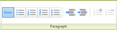
  • Paragraph functionality of bulleted or numbered lists is maintained.
  • Multilevel lists, new to Revit 2017, maintain paragraph functionality but may need to be manually adjusted. (see my previous post on the subject!)
  • Pressing Enter within a formatted paragraph will restore the formatting. 
Enjoy these time saving enhancements to the Revit text editor when exporting from RVT to DWG. Who doesn't want to simplify their workflow and reduce manual editing time?  

To learn more, check out my corresponding video 
to this post, Revit 2017: Improved Text Export to DWG.

And, if you're eager to learn even more about new text features in Revit 2017 be sure to read Revit 2017: Text Size Changes from my colleague and Ideate Senior Software Developer, Ben Bishoff.

Thank you for reading. For more information on the software solutions, training and consulting Ideate provides, please visit the Ideate Inc. website.


Katrina Rodriguez
Ideate AEC Application Specialist
Katrina is an AEC application specialist at the Ideate, Inc. San Francisco office. She is a California–licensed architect with a Bachelor of Science degree in Architecture from the University of the Philippines. Katrina has over 18 years of experience in the AEC industry with a focus on both commercial and hospitality projects. She is also a Revit Certified Professional with over 8 years of experience utilizing the software on both small and large scale projects, from programming to project close out.

Get it. Know it. Use it.

July 21, 2016

Creating Revit Starting Views Using Ideate Sticky & Titleblocks

Having worked with many customers on their BIM workflows and on my own BIM-related projects, one feature I see underused or not used at all, is the Revit Starting View. Especially when combined with a Titleblock and Ideate Sticky, Starting View can be an extremely powerful feature, ensuring team members office-wide have the latest project information.

Starting View allows you to assign a default view Revit will defer to as a starting point when a project file is opened. Even if you save on a completely different view before exiting your file, Revit will open to the Starting View you specifically assign. It is a great way to open directly to a view you are familiar with and want to work from. 

But, choosing your Starting View strategically, matters. 


Most of the Starting Views I have encountered along my way are project landing pages. These landing pages may contain information such as the client name and address, major milestone dates, notes to the team, and other important details related to the project. Unfortunately, most are also created as Drafting Views, which is a missed opportunity; project information is manually entered as a text note, and usually does not correlate to any of the information you see on a Titleblock. So, I say: why not use a customized Titleblock as your Starting View, instead? 

Using a Titleblock as a Starting View means you can add project based information and all edits will automatically propagate throughout your entire project! Additionally, you can add hyperlinks that direct users to project information, such as your BIM Execution Plan or even the Project Directory, itself.

Now throw in Ideate Sticky to get the absolute most out of your Starting View. 


BIM Managers can use Ideate Sticky with their Starting Views and incorporate their Stickies into Revit Templates. One huge advantage of this workflow is the ability to edit a master Sticky with company-wide information, such as current Revit Builds and any other need-to-know project details. When master information is edited, every project in the office will immediately receive an update. When the team opens their Revit projects, they will see the updated information in their Starting View.
To learn more about this workflow and to get some great Starting View tips, be sure to watch my video on the topic.

Thank you for reading. For more information on the software solutions, training and consulting Ideate provides, please visit the Ideate Inc. website.

Sash Kazeminejad
AEC Senior Application Specialist 
Sash is a registered Architect and LEED Accredited Professional who holds a Master of Architecture from Montana State University. Sash’s experience includes project management, BIM management, and design for architectural firms in California, Montana, and Oregon. As an Autodesk Certified Instructor, Sash provides Revit Architecture training and solutions for AECO firms. @sashpdx 

July 18, 2016

Revit 2017: Simplify Models with Revit Parts

I am excited to share a new workflow with you Ideate developed when a valued customer asked the following:

"What is the best workflow if I am creating a shear wall with furring on each side and need to be able to demolish the furring portion, sometimes just on one side? In addition, I want to control the height of each furring wall separately from the core.

Is my only option to create three walls? This gives me what I want to see, 
graphically and I can adjust the height of each wall independently, but now I have to manage three walls, which can be tedious and time consuming."
After pondering what the customer was trying to achieve, the first thing that came to my mind was “Revit Parts!"

In my opinion, Parts is an underutilized tool that can provide you more flexibility with all of the different pieces of your system family assemblies.

To dive into this new workflow, checkout my short video on how to turn your wall assembly into Parts, allowing you to demolish portions of the wall and control the height of each furring wall individually.

Thank you for reading! For more information on Revit and other Autodesk products, and information on training and consulting for the various products Ideate services, please visit our website.


AEC Application Specialist
Emily Clark holds a Bachelor of Architecture degree from Kansas State University, and has over 19 years of experience in the Architecture industry. Her experience includes working for a number of Architecture and Design/ Build firms in the Western United States. She has been a Project Designer, Intern Architect, BIM Manager and Design Technology Manager. She has contributed to the completion of projects ranging from high–end custom residential to Education and Healthcare design. She has worked with multiple platforms and her passion for BIM has enabled her to help transition firms and advance with technology. At Ideate, Emily provides training and support for Revit Architecture.

July 14, 2016

Revit 2017: Reinforcement Connectors

Hi folks, IX here, one of the senior application specialists at Ideate, Inc. I'm back with more talk on reinforcement in Revit 2017.

Another one of my top five features in Revit 2017 is the ability to add 3D reinforcement connector modeling elements to my project. This new feature will improve the level of detail for reinforcement modeling and documentation.

The Reinforcement Connectors are family-based and fully customizable, enabling each team member the ability to use them according to his/her needs, whether it be in schematic design for the structural engineers or shop drawings for the detailers. Rebar Connectors interact with the rebar that they connect to and adapt to changes with the rebar. Additionally, you can add the connectors to groups, assemblies, and partitions with unique coupler numbering. Like other Revit elements will exported to various CAD formats.
To see this new feature in action, check out this short video, Revit Structure 2017: Reinforcement Connectors.

Cheers,
IX


Thank you for reading. For more information on the software solutions, training and consulting Ideate provides, please visit the Ideate Inc. website.

Eugene O'Day, IX
AEC Senior Application Specialist
Eugene A. O’Day, IX, with more than 25 years of architectural and mechanical experience, offers a trained focus on all things Revit and BIM. Teaching is a passion of his. Eugene has been an instructor in undergraduate degree programs, has traveled worldwide teaching Autodesk solutions to major corporations, has taught at accredited ATCs throughout the Northwestern region, and is a frequent and popular instructor, speaker, and presenter for AUGI® CAD Camps, Revit – and related product user groups. He has also been a trusted public school district advisor on new drafting instructor hires. At Ideate, Eugene provides training and support for Revit Architecture, Revit Structure and AutoCAD. Eugene is also a Revit Architecture Autodesk Certified Professional.

July 12, 2016

Revit 2017: New Text Editor Features

By now you've likely already started to play with the exciting new features in Revit 2017's Edit Text contextual ribbon, but I wanted to take this opportunity to provide a quick reference guide for you to use as you continue to familiarize yourself with these helpful additions. In this spirit, I will walk you through the new features, giving you a bird's-eye view of what helpful text editing tools have been added to Revit 2017. 

The New Edit Text Contextual Ribbon
Undo Panel
The Undo Panel allows the undo or redo of a change made to the text without canceling out of the text editing command.
Clipboard Panel
The Clipboard Panel allows the cutting, copying and pasting of text. In previous versions of Revit, the clipboard panel was located in the Modify/Text Notes ribbon and used for cutting, copying and pasting the entire note, as well as cutting, copying and pasting text within a note. Revit 2017 has simplified this by adding a clipboard panel within the Edit Text ribbon, dedicated specifically to editing text within a note.
Font Panel
The Font Panel contains tools for changing text to subscript, superscript, and toggling text from all caps to lower case and vice versa. The new Font Panel also contains some tools from previous versions such the Bold, Italic and Underline, which have been relocated for more efficient editing.
Paragraph Panel
The Paragraph Panel contains tools for creating multilevel lists. Some of the tools are from previous versions - such as the bulleting tools used for removing and adding bullet symbols, numbers, capital and lower case letters. But there are also new tools for creating indentations within text notes, and adjusting already created bullets.
Edit Text Panel
And lastly, there is an Edit Text Panel, which gives users an option to close out of the text editing command. This panel also contains the option to show a border and make the text background opaque when editing.


For a more in depth look at these features, please check out my video, Revit 2017: New Text Editor Features. 

Next, dive into Revit 2017 Text Size Changes with Ideate's Ben Bishoff. 

Thank you for reading. For more information on the software solutions, training and consulting Ideate provides, please visit the Ideate Inc. website.

Katrina Rodriguez
Ideate AEC Application Specialist
Katrina is an AEC application specialist at the Ideate, Inc. San Francisco office. She is a California–licensed architect with a Bachelor of Science degree in Architecture from the University of the Philippines. Katrina has over 18 years of experience in the AEC industry with a focus on both commercial and hospitality projects. She is also a Revit Certified Professional with over 8 years of experience utilizing the software on both small and large scale projects, from programming to project close out.

Get it. Know it. Use it.

June 21, 2016

New to Revit 2017: Reference Plane Subcategories

New to Revit 2017, you now have the ability to add subcategories to your references planes.
Assigning subcategories to your reference planes helps control visibility and graphic settings. Having different colors and linestyles for your reference planes will make it easier to distinguish the different uses for the reference planes. 
View my short video demonstrating how to add subcategories to your reference planes.

Thank you for reading. For more information on Revit and other Autodesk products, and information on training and consulting for the various products Ideate services, visit our website.


AEC Application Specialist
Emily Clark holds a Bachelor of Architecture degree from Kansas State University, and has over 19 years of experience in the Architecture industry. Her experience includes working for a number of Architecture and Design/ Build firms in the Western United States. She has been a Project Designer, Intern Architect, BIM Manager and Design Technology Manager. She has contributed to the completion of projects ranging from high–end custom residential to Education and Healthcare design. She has worked with multiple platforms and her passion for BIM has enabled her to help transition firms and advance with technology. At Ideate, Emily provides training and support for Revit Architecture.

June 20, 2016

Classroom Training - Open Navisworks, Revit and AutoCAD and Classes

Know It. Ideate Training.

Position yourself to land dream projects. Tap the full potential of your software solutions. Increase your facility, fluidity and capability to maximize the value of your precision software tools.
7.6-7.7::San Francisco
Navisworks Fundamentals
7.12-7.14::San Jose
Revit Architecture Fundamentals
7.12-7.14::San Francisco
Revit Structure Fundamentals
7.18-7.20::San Francisco
Civil 3D Fundamentals
7.19-7.21::Sacramento
AutoCAD Fundamentals
7.19-7.21::Portland
Revit Architecture Fundamentals
7.26-7.27::San Jose
Civil 3D for Surveyors
Know your software. Sign up now! 

Contact the Ideate Training Department at 888.662.7238 x1012 or education@ideateinc.com

June 16, 2016

Model In-Place: Prefabricated Non-Planar Building Modules

A Component Model in-Place workflow is typically touted as a one-off solution for when you have a custom situation in a projectnot addressed by system or loadable families, such as a curved roof or ceiling or a serpentine wall – but what if the built-in solution repeats?

The scenario covered here is for a repeatable prefabricated, modular unit, as initially explored by Eileen Gray in her Maison Elliptique (1936), where three or four prefabricated modules are combined to make a home. 

Revit lets you create an in-place family for the required categories (Roof with Ceiling) but editing them can be problematic because each copied in-place family – unlike normal Revit families – is unique. Objects created belong to the datum objects (reference plane) they are created on. This makes it difficult to edit a copied in-place family. 

A solution is to create a Group from the in-place family for copying and then to ungroup them for unique editing. 
Two Modules With Opening
The in-place families can be grouped, copied, ungrouped and edited to add more modules. 
Four Modules With Opening
For more detail on how to group and upgroup families for editing, watch my video Model In-Place: Prefabricated non-planar building modules.

For information on training and consulting for the various products Ideate services, visit our website. Also check our blog for continued solutions as we encounter them.

AEC Senior Application Specialist
Jim Cowan’s extensive AEC design industry experience, Autodesk design solutions expertise and status as an Autodesk Certified Instructor have made him a sought after University Curriculum developer, instructor and presenter. Jim’s areas of expertise include eLearning, interoperability between solutions and overcoming barriers to the adoption of Building Information Modeling (BIM). Educated in Architecture at Edinburgh College of Art/Heriot–Watt University and in Landscape Architecture at the University of Manitoba, Jim has special focus on sustainability issues: daylight analysis, sun studies, lighting analysis, modeling buildings and conceptual energy modeling (models with shading devices). You can learn more from Jim on his YouTube Channel.