September 13, 2016

Interoperability: Image Sequences for Easy Editing

Did you know can create and save a sequence of images from 3ds Max as a single file (AVI or MOV)?

By combining the best features from Revit and 3ds Max it is possible to edit specific frames (images) within a movie. From Revit we get the required, linked building elements with their materials, and from 3ds Max we get the ability to render a sequence of PNG files. This workflow saves us the trouble of having to re-rendering the whole movie, say after removing reflecting materials, or making other edits.
In this video tutorial, Interoperability: Image Sequencing for Easy Editing, only the first 40 images of a 900 image sequence needed to be fixed. The first sequence had a reflective paver material that took 40 minutes to render in one frame. The second, “fixed,” sequence used a matte material that took about 20 minutes to render in one frame.
First Sequence with relective paver material
Second, fixed, sequence with matte paver material
The building used for this example is a proposed prefabricated house, designed by Lt. Russell M. Amdal and featured in Art and Architecture Case Studies, 1945.

For more information on the software solutions, training and consulting Ideate provides, please visit the Ideate Inc. website.

AEC Senior Application Specialist
Jim Cowan’s extensive AEC design industry experience, Autodesk design solutions expertise and status as an Autodesk Certified Instructor have made him a sought after University Curriculum developer, instructor and presenter. Jim’s areas of expertise include eLearning, interoperability between solutions and overcoming barriers to the adoption of Building Information Modeling (BIM). Educated in Architecture at Edinburgh College of Art/Heriot–Watt University and in Landscape Architecture at the University of Manitoba, Jim has special focus on sustainability issues: daylight analysis, sun studies, lighting analysis, modeling buildings and conceptual energy modeling (models with shading devices). You can learn more from Jim on his YouTube Channel.

September 8, 2016

Where Are My Callout Tags?

One of the biggest issues us Revit users run into is, of course, missing elements.

I am sure each of you have scratched your head a time or two wondering where in the world certain items are. Specifically, when dealing with Callouts and Sections there is a parameter that controls which views those particular callouts will appear in, based on the scale of the view.


Callout Views


When you create a Callout View you have the option to create a parent view or a detail view. In the View Properties for the callout detail view you have a parameter called Show In. This parameter controls whether this callout shows in the parent view only, or in intersecting views, as well. 
(Please note this visibility option only applies to detail callout view and not floor plan callouts.) 

When the Show In value is Parent View Only, Hide at Scales Coarser Than will be read-only. When the Show In value is Intersecting Views, you can change the value of the Hide at Scales Coarser Than parameter. As a result, Revit displays the callout tag in any view that intersects the parent view perpendicularly, as long as the view scale is more detailed than the scale specified by Hide at Scales Coarser Than.


Section Views

Section Views do not have the Show In 
parameter, however they do have Hide at Scales Coarser Than. The section instance parameter Hide at Scales Coarser Than establishes a scale at which sections are either shown or hidden in other views. For example, a section tag can be hidden at scales coarser than 1/4”=1’0”.


IdeateApps Xray

Another great tool if you are missing elements in your view is the new IdeateApps tool, Ideate XRay, it will find the hidden callouts and tell you exactly where and why they are hidden, including the parameters discussed above.


Download your free, fully functioning IdeateApps trial here.
To learn more, and see these parameters in action, check out my video, Where Are All My Callout Tags?

Thank you for reading. For more information on the software solutions, training and consulting Ideate provides, please visit the Ideate Inc. website.

AEC Application Specialist
Emily Clark holds a Bachelor of Architecture degree from Kansas State University, and has over 19 years of experience in the Architecture industry. Her experience includes working for a number of Architecture and Design/ Build firms in the Western United States. She has been a Project Designer, Intern Architect, BIM Manager and Design Technology Manager. She has contributed to the completion of projects ranging from high–end custom residential to Education and Healthcare design. She has worked with multiple platforms and her passion for BIM has enabled her to help transition firms and advance with technology. At Ideate, Emily provides training and support for Revit Architecture.

September 6, 2016

Interoperability: Animated 3d Studio Max AEC Objects and Revit Models

Only a camera can be animated within Revit, but we often need opening doors, windows or other animated objects in a presentation. This workflow shows how we can reuse our Revit model, minus doors, plants and people, and add animatable objects from 3d Studio Max. The model we will be using as an example is a prefabricated house as proposed by Lt. Russell M. Amdal, Art and Architecture Case Studies, 1945. 

By combining the best features of both products we get, from Revit, the majority of the required building elements, and the AEC objects from within 3d Studio Max. We can use their parametric properties to animate them – such as the angled opening of the door.
This example shows a 3d Studio Max pivot door in the door opening that can be animated.
For a close-up look at this workflow, watch my video Interoperability: Animated 3d Studio Max AEC Objects and Revit Models.

Thank you for reading. For more information on the software solutions, training and consulting Ideate provides, please visit the Ideate Inc. website.


AEC Senior Application Specialist
Jim Cowan’s extensive AEC design industry experience, Autodesk design solutions expertise and status as an Autodesk Certified Instructor have made him a sought after University Curriculum developer, instructor and presenter. Jim’s areas of expertise include eLearning, interoperability between solutions and overcoming barriers to the adoption of Building Information Modeling (BIM). Educated in Architecture at Edinburgh College of Art/Heriot–Watt University and in Landscape Architecture at the University of Manitoba, Jim has special focus on sustainability issues: daylight analysis, sun studies, lighting analysis, modeling buildings and conceptual energy modeling (models with shading devices). You can learn more from Jim on his YouTube Channel.

September 1, 2016

Revit 2017: Filling Gaps in a Revit Fabrication Model

Fabrication detailing in Revit 2017 supports different MEP detailing workflows. In this post, I'll provide a brief rundown for each.

For each fabrication model you must specify a fabrication configuration and load services. You can then place parts to create a detailed fabrication model in Revit, or convert an existing Revit model with generic duct, pipe, and electrical containment parts to a model that uses fabrication parts.

Continue to add fabrication parts and modify the elements in the model as needed. For all those new to the feature this can be found on the Systems tab > Fabrication Part:

Content: 

Download sample fabrication configurations for use with the MEP features of Revit. The sample fabrication configurations contain generic US Imperial and UK Metric content.

Download the Imperial and Metric sample configurations

  1. Click the file names: www.autodesk.com/revit-2017-mep-fab-sample-content-imperial and www.autodesk.com/revit-2017-mep-fab-sample-content-metric.
  2.  
  3. Open the files. The files are installed to:
  • C:/Users/Public/Documents/Autodesk/Fabrication /Revit MEP Imperial Content/Vx.xx
  • C:/Users/Public/Documents/Autodesk/Fabrication /Revit MEP Metric Content/Vx.xx
However, to access and use a full set of real-world content, I would suggest an installation of any of the Autodesk Fabrication products:
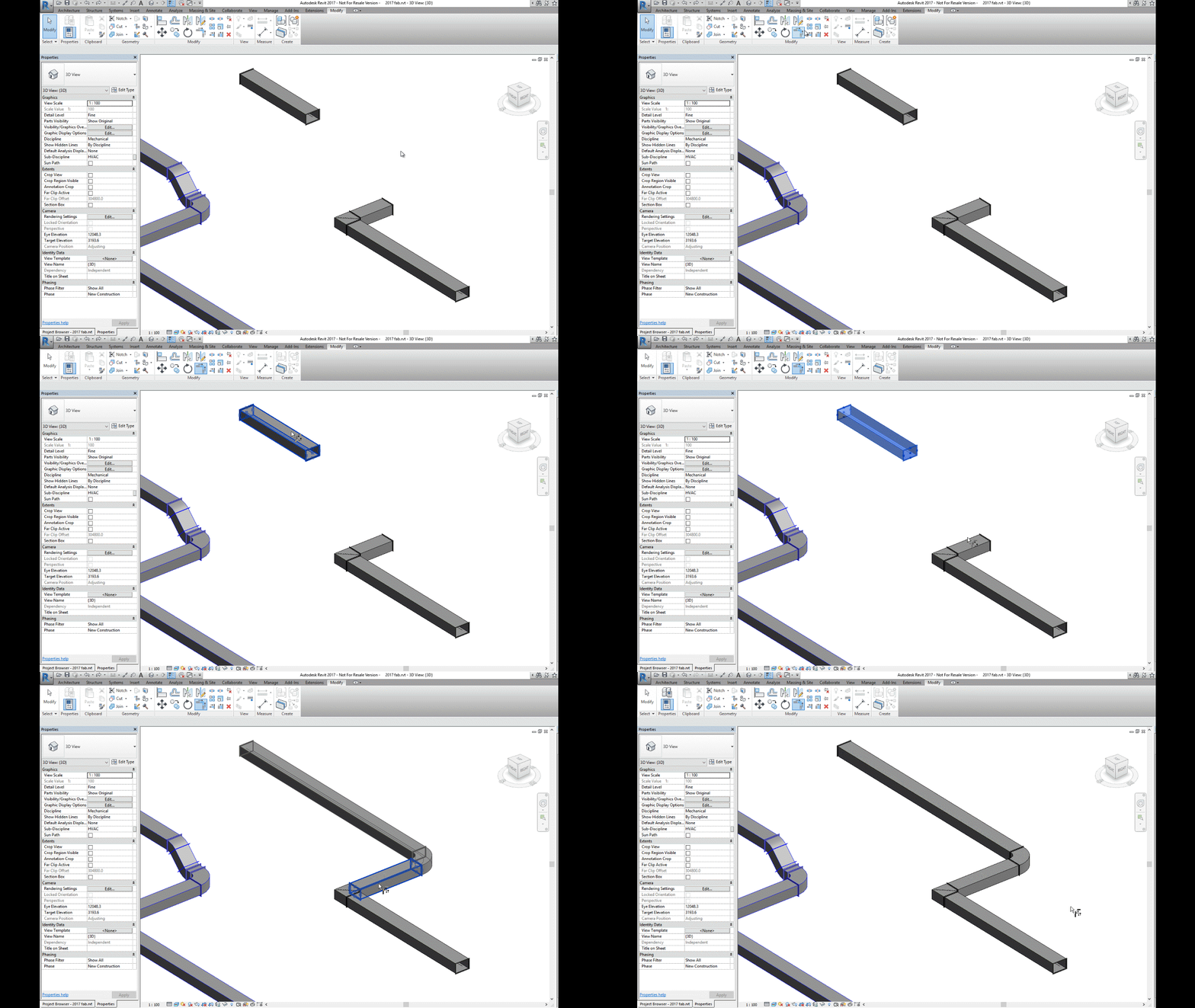
Trim and Extend:

Use the Trim/Extend tool to fill a gap between two straights, For example, when connecting a duct branch to a main or pipework to a header:

Quick Connect:

Use the Quick Connect tool to fill a gap between a fitting and another straight where no additional fittings are needed. 


Please note: the Quick Connect command is available only when a fitting is selected. The command is disabled when a straight is selected. You can use this tool to drag the connector onto another part to connect them:

Route & Fill:

Use the Route and Fill tool to add parts between two open connectors in a faster, more efficient way than placing parts one-by-one. The Route and Fill tool provides one or more solution depending on the service. You can narrow the number of solutions by filtering the fittings used, switch direction of the route, and even filter the solutions to force it to use certain parts:

Per the Autodesk help file, one thing to remember with this feature is that “A route must exist in a single plane. Solutions that require two planes or three bends are not supported.” This means varying height connections that also require bends will not automatically connect. It may be quicker using the “Design to Fabrication” feature for these situations.

Design to Fabrication:

Use the Design to Fabrication tool to convert a design model with Revit elements to a fabrication model with LOD 400 fabrication parts.

You can convert selected parts, or an entire duct or pipe network. The Design to Fabrication tools provide a more efficient workflow, since the fabrication model does not need to be redrawn from scratch. The result of the conversion is based on the design line algorithm used by the Autodesk Fabrication products, and uses the same content available in the Autodesk Fabrication products:

It's important to note, this is a one-way process; once the Revit MEP Design has been converted to Fabrication Parts, it cannot be reversed. I would suggest using a copy of the MEP Design to convert, as this gives us the benefit of linking the projects for comparison.

Swap Parts:


In 2017 we now have the ability to swap Fabrication parts in the same way as Revit Families:

Optimize Lengths:

This feature allows you to optimize the straight lengths of generic ductwork by adding, removing, or modifying lengths of straight segments.


Please Note: If a straight is pinned, or part of a group, it will not be optimized.

To go in-depth with each of these features, check out my videos in the Revit Architecture, Revit MEP and Revit Structure 2017 playlist on Ideate Inc.'s YouTube Chanel.

Thank you for reading. For more information on the software solutions, training and consulting Ideate provides, please visit the Ideate Inc. website.

Senior Application Specialist MEP/AEC Solutions
Bill has over 25 years experience in applying MEP & AEC design solutions for large commercial companies, this has led to actively develop Autodesk® Revit® implementation strategies, techniques, and procedures for architectural and MEP companies. He has worked for TEECOM Design Group, GTE/GTEL, Greg LeDoux and Associates, and Scottish Power in England. Bill is an Autodesk MEP Implementation Certified Expert, and has been the Lead Designer for several multimillion dollar communication sites which have included structural, electrical, HVAC, conduit, cable plans and equipment layouts. He graduated from the Pasadena Institute of Technology and has a Sustainable Design Certification from the University of California at Berkeley.