Ideate, Inc. is pleased to show a greatly improved workflow for data management with Ideate BIMLink. In addition to being able to push and pull data from a Revit® Building Information Model (BIM) to a regular Excel® spreadsheet, you can host the sheet on Google Docs and use Google Sheet to provide worldwide simultaneous access to the sheet BIM data. Anyone can use the Google Doc App or a link to access the sheet collaboratively and simultaneously and then with the use of Ideate BIMLink, can publish that same information back to the Revit model.
The benefits of this realtime collaboration in the cloud include a security and notification system, so that you can control who has access to the sheet and whether they can review, comment or edit. The version control features allow for historic rollbacks to previous versions.
Take your Revit data to the cloud with Ideate BIMLink and Google Sheet.
Google and the Google logo are registered trademarks of Google Inc., used with permission.
Jim Cowan
Ideate AEC Application Specialist
Jim Cowan’s extensive AEC design industry experience and Autodesk design solutions expertise have made him a sought after university curriculum developer, instructor and presenter. Jim’s areas of expertise include interoperability between solutions and overcoming barriers to the adoption of Building Information Modeling (BIM). Educated in Architecture at Edinburgh College of Art/Heriot-Watt University and in Landscape Architecture at University of Manitoba, Jim has special focus on sustainability issues: daylight analysis, sun studies, lighting analysis, modeling buildings and conceptual energy modeling (models with shading devices). YouTube Channel: MrJimCowan
Get it. Know it. Use it.
Showing posts with label ADSK2014. Show all posts
July 25, 2013
July 24, 2013
The Pain of Jobsite Inspections
All of us who have gone to a jobsite to do an inspection, whether as the Architect doing a contract required review, or as part of a construction team (Construction Manager/Superintendent), or as an Owner’s representative; the process has always been the same. Carry to the jobsite all the drawings and a camera, maybe a recorder, but always your trusty pad and pen to record the issues/concerns and notes required. I speak of this experience because the jobsite visits are engraved into my brain as having one ever-lasting memory – that of frustration.
BIM360 Field has benefits for Architects (who do jobsite review), General Contractors, and Subcontractors (who have large teams on a site). Owners who take an active role in construction activities can also find great benefit. For further information, visit our website (http://www.ideateinc.com/products/bim_360_field.html).
Ideate, Inc. is an Autodesk VAR, one of a select number of Autodesk resellers who have be selected to sell Autodesk BIM360 Field to customers. Call us at 888-662-7238, or talk to your Ideate Account Manager about discussing Autodesk BIM360 and your needs. (www.ideateinc.com).
David Haynes, NCARB, PMP, LEED AP
Ideate Director of Consulting
David is a Registered Architect, Project Management Certified Professional, who previously had his own architectural practice and was President of a commercial design-build construction company for 15 years. A graduate of University of Arizona, he has worked as an Architect, contractor, developer and as a national construction manager for a national retailer. David currently provides business process analysis, virtualization and change management solutions for AEC clients across the United States involved in the design and building industry. Follow David on Twitter: @dhaynestech
Get it. Know it. Use it.
Frustration of having to first record, then document, then usually having to input the information into the computer; then comes the real frustration – do it all over again in the next inspection. There must be a better way!There is a solution. Autodesk BIM360 Field provides a solution that fits today’s technology and jobsite-specific issues. Autodesk BIM360 Field provides a Web and Tablet based (iOS) construction jobsite information management system. Checklists/Punchlists, Equipment/Assets, Reports, and Issues are all tracked from a tablet, while being able to record/document jobsite conditions.
Why should you care?
• How much time are you, or your company, spending writing and re-writing lists, and then distributing them to the project team. Count the hours – they rack up each month.
• Have you ever left important information back at the office (a specific set of plans, or shop drawings). That is a waste of precious time.
• Have you not had the most up to date information at the jobsite and made judgments/decisions based upon out of date information – that is certainly risky.
• Have you ever wondered if an issue got resolved, who resolved it, and when? Lack of accurate, timely information (data) can lead to rework, redo, re-decide and other time delays. Delays cost money.The great thing about BIM360 Field is that you don’t need to be BIM-enabled (though if you are, there are some additional benefits). If you currently work with 2D plans, and using pad and pen to document jobsite events/issues/concerns – look into BIM360 Field. The costs are reasonable - the value is great.
BIM360 Field has benefits for Architects (who do jobsite review), General Contractors, and Subcontractors (who have large teams on a site). Owners who take an active role in construction activities can also find great benefit. For further information, visit our website (http://www.ideateinc.com/products/bim_360_field.html).
Ideate, Inc. is an Autodesk VAR, one of a select number of Autodesk resellers who have be selected to sell Autodesk BIM360 Field to customers. Call us at 888-662-7238, or talk to your Ideate Account Manager about discussing Autodesk BIM360 and your needs. (www.ideateinc.com).
David Haynes, NCARB, PMP, LEED APIdeate Director of Consulting
David is a Registered Architect, Project Management Certified Professional, who previously had his own architectural practice and was President of a commercial design-build construction company for 15 years. A graduate of University of Arizona, he has worked as an Architect, contractor, developer and as a national construction manager for a national retailer. David currently provides business process analysis, virtualization and change management solutions for AEC clients across the United States involved in the design and building industry. Follow David on Twitter: @dhaynestech
Get it. Know it. Use it.
July 23, 2013
What's New in Revit MEP 2014: I have a different View than you! - Ability to assign Temporary View Templates in Revit.
Revit 2014 in general has some great enhancements, one that, in my opinion, that will be used a lot is the ability to assign temporary view template overrides to the "assigned" View Template per view.
The assignment itself is a basic two step process:
One of the common frustrations that we at Ideate, Inc. deal with in the improved Revit 2013 View Templates is the inability of individuals to make quick changes to the view, due to it being "locked" to a view template.
Selecting “Temporarily Apply Template Properties…” enables you to enter the mode with a current view template applied to the view properties. This enables the mode to be started from a known state.
This improves documentation and design visualization with ability to change view properties without affecting the saved view state.
Bill Johnson
Ideate Senior MEP Application Specialist
The assignment itself is a basic two step process:
1. Select a view template to apply as a temporary state
2. Then any property associated with view templates can be modified, but not saved
One of the common frustrations that we at Ideate, Inc. deal with in the improved Revit 2013 View Templates is the inability of individuals to make quick changes to the view, due to it being "locked" to a view template.
Temporary View Properties is a new platform feature that allows you to change view properties without affecting the saved view state. Starting the mode allows changes to the view to meet your current workflow. These changes will not affect the view for printing and will not cause issues while collaborating via worksharing. Using the feature may reduce the need for saving and maintaining working views, although that is not the primary use case.
Selecting “Temporarily Apply Template Properties…” enables you to enter the mode with a current view template applied to the view properties. This enables the mode to be started from a known state.
The menu saves the last 5 view templates that have been used when activating the mode. Once the mode is activated a frame is drawn around the view with the title, “Temporary View Properties” to indicate that the view is temporary.
Ideate Senior MEP Application Specialist
Bill has over 20 years experience in applying AEC design solutions for large commercial companies. A graduate of Pasadena Institute of Technology, he has worked for TEECOM Design Group, GTE/GTEL, Greg LeDoux and Associates, and Scottish Power in England. Bill has also had the opportunity to act as Lead AutoCAD Designer for multimillion dollar communication sites which have included structural, electrical, HVAC, conduit, cable plans and equipment layouts. He has a Sustainable Design Certification from the University of California at Berkeley.
Get it. Know it. Use it.
July 22, 2013
What's New in AutoCAD MEP 2014: What is your "Standard" - Enhanced Layer Standard NCS 5.0
At Ideate, we’ve been reviewing the Autodesk 2014 product line and sharing new features and enhancements that we think will benefit users. AutoCAD MEP 2014 has some solid enhancements, one of the ones that will give companies and users additional flexibility is the Layer Standards and Layer Key Styles compatible with the new US standard - NCS 5.0.
Autodesk created the NCS 5.0 Layer Standard, NCS 4.0 Layer Standard, and 3.1. They had several goals to accomplish. Bring AutoCAD MEP up to date with NCS 5.0 Layer Standard. Make AutoCAD Architecture and MEP both use the same Layer Standard and Layer Key Style for consistency. Some companies standardize on a ALL CAPITAL LETTER layer format, and some on a Title Case format.
The MEP layer standard accommodates the NCS standard, with some flexibility (optional front status, and extra Minor3). The primary change in 2014, is the Field values match NCS 5.0 values everywhere possible (exception being the additional MEP values that support our content). Autodesk updated the layer values on the keys, so that they accommodate the NCS 5.0 values where applicable. That was huge in MEP, because back in 2007 they had Minor1 values that were only 3-characters. There is now the enhancement to have 4-character values in Minor1 everywhere in MEP.
This new enhanced Layer Standard drawing features:
Bill Johnson
Ideate Senior MEP Application Specialist
Autodesk created the NCS 5.0 Layer Standard, NCS 4.0 Layer Standard, and 3.1. They had several goals to accomplish. Bring AutoCAD MEP up to date with NCS 5.0 Layer Standard. Make AutoCAD Architecture and MEP both use the same Layer Standard and Layer Key Style for consistency. Some companies standardize on a ALL CAPITAL LETTER layer format, and some on a Title Case format.
The MEP layer standard accommodates the NCS standard, with some flexibility (optional front status, and extra Minor3). The primary change in 2014, is the Field values match NCS 5.0 values everywhere possible (exception being the additional MEP values that support our content). Autodesk updated the layer values on the keys, so that they accommodate the NCS 5.0 values where applicable. That was huge in MEP, because back in 2007 they had Minor1 values that were only 3-characters. There is now the enhancement to have 4-character values in Minor1 everywhere in MEP.
This new enhanced Layer Standard drawing features:
o Ability to generate the correct layer names more easily
o New layer standard and layer key styles
o NCS 5.0-compliantThe bottom line is for those firms that follow the NCS 5.0, you will no longer need to modify layer names manually to comply with NCS 5.0.
Ideate Senior MEP Application Specialist
Bill has over 20 years experience in applying AEC design solutions for large commercial companies. A graduate of Pasadena Institute of Technology, he has worked for TEECOM Design Group, GTE/GTEL, Greg LeDoux and Associates, and Scottish Power in England. Bill has also had the opportunity to act as Lead AutoCAD Designer for multimillion dollar communication sites which have included structural, electrical, HVAC, conduit, cable plans and equipment layouts. He has a Sustainable Design Certification from the University of California at Berkeley.
Get it. Know it. Use it.
July 16, 2013
What's New in Revit MEP 2014: Parameter Variance for Groups - Ability to have parameters vary for groups!
Revit MEP 2014 has some great enhancements, one of the most unique is the ability to have parameters vary by groups. One of the most common frustrations that clients have is the inability to schedule "groups" within Revit and we have suggested several different "workarounds" during support case issues at Ideate, Inc.
However with this minor enhancement it will open up more opportunities to push data into elements within groups and allow us to schedule this data. The reason for this, is we can use the “new variance parameter by group” functionality in 2014.
For example, when creating an instance project parameter (Text, Area, Volume, Currency, Mass Density, URL, Material, and <Family Type> only), you now have the option to allow the value to vary for different group instances. The user can edit the parameter value for an element in a group instance without changing the value for corresponding elements in other group instances.
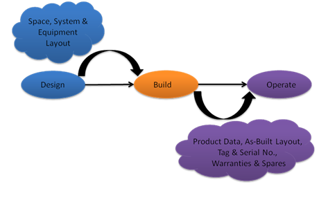
Since you can vary the value of parameters assigned to groups, this will provide more flexible data reporting and increased support for COBie requirements. Data can also be incorporated into the operation and maintenance phase of a building lifecycle more efficiently.
Bill Johnson
Ideate Senior MEP Application Specialist
However with this minor enhancement it will open up more opportunities to push data into elements within groups and allow us to schedule this data. The reason for this, is we can use the “new variance parameter by group” functionality in 2014.
For example, when creating an instance project parameter (Text, Area, Volume, Currency, Mass Density, URL, Material, and <Family Type> only), you now have the option to allow the value to vary for different group instances. The user can edit the parameter value for an element in a group instance without changing the value for corresponding elements in other group instances.
Since you can vary the value of parameters assigned to groups, this will provide more flexible data reporting and increased support for COBie requirements. Data can also be incorporated into the operation and maintenance phase of a building lifecycle more efficiently.
Ideate Senior MEP Application Specialist
Bill has over 20 years experience in applying AEC design solutions for large commercial companies. A graduate of Pasadena Institute of Technology, he has worked for TEECOM Design Group, GTE/GTEL, Greg LeDoux and Associates, and Scottish Power in England. Bill has also had the opportunity to act as Lead AutoCAD Designer for multimillion dollar communication sites which have included structural, electrical, HVAC, conduit, cable plans and equipment layouts. He has a Sustainable Design Certification from the University of California at Berkeley.
Get it. Know it. Use it.
July 15, 2013
Improved Stair Functionality in Revit 2014
Throughout the Ideate series of Revit 2014 Blogs and Videos Ideate has introduced a number new functionalities within the Revit product. In continuation of this series Ideate brings you an improvement to the component stairs introduced in Revit 2013. Stairs and railings are a continuing multi-year project with this year's improvements being made to seven areas within the component stairs.
Additional Location Line options: Revit 2013 introduced the ability of sketching component stairs by selecting a location line other than the center of the run. Specifying the left or right side of the stair run allowed designers to sketch a run of stair along a wall. New to Revit 2014, two additional location line options are available and the three existing location lines readjusted. Location lines now include Exterior Support: Left, Run: Left, Run: Center, Run: Right, and Exterior Support: Right. Now designers are able to sketch on the exterior sides of stair support elements, on either side of a run, or down the center of the run, opening up a number of options for sketching stair runs. Figure 1.

Modify the Landing Shape: Automatic Landings include new control grips to modify the landing leg length. This is the point where the landing connects to the run. Figure 3.
Automatic Landing Reshaping Behavior: Initially when an automatic landing is created, the edge of the automatic landing remains flush with the edge of a stair run. In Revit 2014, control grips are available along the edges of the landing to change the shape of the landing. Additionally modifying a run will also modify the landing shape . Figure 3.

Figure 3
Automatic Landing Creation: When creating a U-shaped/switchback stair that includes varying run widths, the automatic landing is initially created with a depth equal to the width of the narrowest run. The landing depth can be modified after the stair runs and landing are created through the control grips along the edges of the landing.
Accurate Modifications: Temporary dimensions are now available when modifying a run's width, the landing depth on a U-shaped/switchback stair, the radius of a spiral stair, and the distance between stair components. At the time of run creation, listening dimensions are available for both straight runs and arc runs. Figure 4.
Figure 4
Snapping reference Improvement: More snapping capabilities are available during the creation and modification of stair components. For example, run to run vertical, horizontal, parallel, and perpendicular snapping is available when dragging the stair path end point. Figure 5.
Figure 5
Ron Palma
Ideate AEC Application Specialist
Ron has over 24 years of experience in the architectural industry as a drafter, designer, lead project designer, trainer, and a CAD manager implementing Autodesk Architectural Solutions for a residential design firm. His instructional background includes being an Autodesk Certified Instructor, trainer, support technician, educator at Portland and Clackamas Community Colleges, as well as a U.S. Army certified instructor where he was a senior instructor at Ft Lewis Washington. Ron is a member of the Oregon Army National Guard and platoon sergeant, training and mentoring soldiers in their careers. Ron is a published writer and continues to author professional technical training manuals and shorts for AutoCAD, AutoCAD Architecture, and Revit. As an Autodesk Certified Instructor, Ron provides Revit Architecture training and support for AEC firms. Follow Ron @RonPalmaAEC.
Get it. Know it. Use it.
Additional Location Line options: Revit 2013 introduced the ability of sketching component stairs by selecting a location line other than the center of the run. Specifying the left or right side of the stair run allowed designers to sketch a run of stair along a wall. New to Revit 2014, two additional location line options are available and the three existing location lines readjusted. Location lines now include Exterior Support: Left, Run: Left, Run: Center, Run: Right, and Exterior Support: Right. Now designers are able to sketch on the exterior sides of stair support elements, on either side of a run, or down the center of the run, opening up a number of options for sketching stair runs. Figure 1.

Figure 1
Modify the run width before or after stair creation: Prior to Revit 2013, the width of a stair run could be set in the Properties Palette. In Revit 2013, the minimum run width was set in the stair's Type Properties. In Revit 2014, the width of the stair can be set in the Actual Run Width option in the Options bar. Additionally after a run is created, it can be selected in it's sketch mode and the width of the run modified with grips or by using a width temporary dimension. Figure 2.

Figure 2
Modify the Landing Shape: Automatic Landings include new control grips to modify the landing leg length. This is the point where the landing connects to the run. Figure 3.
Automatic Landing Reshaping Behavior: Initially when an automatic landing is created, the edge of the automatic landing remains flush with the edge of a stair run. In Revit 2014, control grips are available along the edges of the landing to change the shape of the landing. Additionally modifying a run will also modify the landing shape . Figure 3.

Figure 3
Automatic Landing Creation: When creating a U-shaped/switchback stair that includes varying run widths, the automatic landing is initially created with a depth equal to the width of the narrowest run. The landing depth can be modified after the stair runs and landing are created through the control grips along the edges of the landing.
Accurate Modifications: Temporary dimensions are now available when modifying a run's width, the landing depth on a U-shaped/switchback stair, the radius of a spiral stair, and the distance between stair components. At the time of run creation, listening dimensions are available for both straight runs and arc runs. Figure 4.
Figure 4
Snapping reference Improvement: More snapping capabilities are available during the creation and modification of stair components. For example, run to run vertical, horizontal, parallel, and perpendicular snapping is available when dragging the stair path end point. Figure 5.
Figure 5
Ron Palma
Ideate AEC Application Specialist
Ron has over 24 years of experience in the architectural industry as a drafter, designer, lead project designer, trainer, and a CAD manager implementing Autodesk Architectural Solutions for a residential design firm. His instructional background includes being an Autodesk Certified Instructor, trainer, support technician, educator at Portland and Clackamas Community Colleges, as well as a U.S. Army certified instructor where he was a senior instructor at Ft Lewis Washington. Ron is a member of the Oregon Army National Guard and platoon sergeant, training and mentoring soldiers in their careers. Ron is a published writer and continues to author professional technical training manuals and shorts for AutoCAD, AutoCAD Architecture, and Revit. As an Autodesk Certified Instructor, Ron provides Revit Architecture training and support for AEC firms. Follow Ron @RonPalmaAEC.
Get it. Know it. Use it.
Subscribe to:
Posts (Atom)