

Modifying the Panel Family
The panel family controls which style of panel schedule will be used in the report. To change, this, select the panel in the project, right-click and select Edit Family:

Within the Family Editor, change the value of Panel Configuration in the Properties palette from Two Columns, Circuits Across to One Column:

Creating New Panel Schedule Report
Then before you can use the new configuration, you’ll have to delete existing panel schedules based on that panel family – to do this, locate them in the Project Browser, right-click and select Delete:


In this example, there are a couple more adjustments that need to be made. For example, you may want to replace the phase column headers from “A,” “B” and “C” to “L1,” “L2” and “L3” respectively, and we can increase the number of circuits from 21 to 24, to match the slots/ways on our panel.
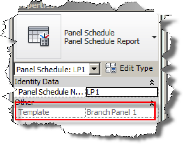
These changes need to be made in the panel schedule template. To know which template is being used, select the appropriate schedule in the Project Browser:


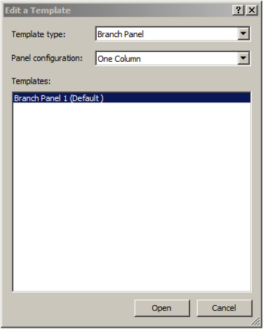


The additional rows will be added to the template, then select Finish Template from the ribbon to save the changes. In order to see the changes, it is then necessary to delete the original panel schedule report (via the Project Browser) and then once again use Create Panel Schedule to re-write the panel schedule with the new template.

Bill Johnson
Ideate Senior MEP Application Specialist
Bill has over 20 years experience in applying AEC design solutions for large commercial companies. A graduate of Pasadena Institute of Technology, he has worked for TEECOM Design Group, GTE/GTEL, Greg LeDoux and Associates, and Scottish Power in England. Bill has also had the opportunity to act as Lead AutoCAD Designer for multimillion dollar communication sites which have included structural, electrical, HVAC, conduit, cable plans and equipment layouts. He has a Sustainable Design Certification from the University of California at Berkeley.
Get it. Know it. Use it.