Showing posts with label AutoCAD 2016. Show all posts

February 25, 2016

AutoCAD 2016 Xref Layer Override Enhancements

Here at Ideate, I’ve been looking over the new features in AutoCAD 2016. One of the new features is the drawing based XREFOVERRIDE variable. You may have noticed that the xref controls are behaving differently in Autocad 2016. This new system variable may be the cause. 

What this variable does is give the user the ability to force object properties in xrefs to be set to ByLayer. If you’ve ever had to open up all of your Xref’s to manually change object properties to ByLayer, this variable is going to save you a lot of time.  

If you haven’t noticed this change, it is because the default state is set to 0, which is the pre-2016 behavior we are all used to. To turn this variable on, set it to 1. To reiterate, when the variable is set to 1 all objects within an xref’ed drawing will behave as if their properties are set to bylayer. When the variable is set to 0, the objects retain their properties regardless of what you have set as their layer properties. Since this variable is drawing specific, it can be set differently in each drawing.

In the layer panel on the home tab of the ribbon, and in the layer manager dialog box, you can change the properties of the layers. Xref’ed layers will be greyed out, however you can override their original properties here. If the XREFOVERRIDE variable is set to 1, all objects on the xref’ed layer will reflect the layer properties.  
Layer Manager
For more information on AutoCAD, as well as training and consulting for the various products Ideate services, visit our website at www.ideateinc.com. Also, keep checking back on the blog for continued solutions as we encounter them.

Kate Ming
AEC Application Specialist

Kate is a California licensed civil engineer with a BS in Civil and Environmental Engineering from UC Berkeley. Prior to Ideate, she worked at a multinational company for four years doing general civil design on large infrastructure projects. She is versed in roadway, rail, utility design and site development. She also has experience with utility demand analysis and Low Impact Development plans. As a Civil 3D Autodesk Certified Professional Kate provides training and support for Civil 3D, AutoCAD, and InfraWorks.

December 4, 2015

Autodesk AutoCAD 2016 System Variable Monitor

 
As an Application Specialist at Ideate I provide technical support to our customers besides teaching and mentoring.   An occasional issue that AutoCAD users experience is a random change to a system variable. Interestingly, while mulling over what feature to blog about, I got a text message about the very same issue. A former coworker stated that his Open Drawing dialog box no longer pops up in Land Desktop 2006. All he gets is a command line prompt to enter the filename and path.  He couldn't remember the system variable. Do you know what system variable controls the appearance of the open drawing dialog?  If No, that's OK. I wouldn't remember if it did not "pop up" in tech support. It is FILEDIA. The value should be 1. It gets reset to 0 many times after a crash.

Well, with AutoCAD 2016 based products, you have a new helper that monitors whether those pesky system variables change on you.  It's appropriately called the System Variable Monitor.  How do you get to it?  Let's take a look.

Type SYSVARMONITOR in the command line (no ribbon icon) to bring up the System Variable Monitor Dialog. 


System Variable Monitor Dialog
You may notice that the setting for Enable balloon notification is unchecked.  This is the default. AutoCAD will notify you of a monitored variable change via the command line and through the appearance of an icon at the far right of your drawing status bar.


System Variable Monitor Icon Notification

This may be fine if a change occurs while you are in a drawing, but if the change occurs while AutoCAD is closing, you'll only see the icon.  Want a more obvious notification?  Then we need to enable balloon notification. 

Now we'll get "Warning Will Robinson…Warning!" when a change occurs…almost.


System Variable Changed Balloon Notification
 
Several common system variables are already in the monitored list, including our friend FILEDIA.  You can add other system variables by selecting the Edit List button.  Then select the desired variable from the left pane. Select the highlighted chevron to add it to the monitored list and hit then OK.


Edit System Variable List Dialog

With the new System Variable Monitor in AutoCAD 2016, you can be confident that you won't be pulling your hair out and wasting time when FILEDIA or another variable changes on you.  That's good news. Now, if I can only convince my former coworker to upgrade from 2006 to 2016. 
 
 
Thank you for reading. For more information on AutoCAD and other Autodesk products, and information on training and consulting for the various products Ideate services, visit our website at www.ideateinc.com.


ENI Application Specialist

Daniel is an Application Specialist for Infrastructure Solutions at the Ideate Sacramento office. He is a California licensed Civil Engineer and LSIT with over 9 years land development design experience and 6 years Civil–GIS software consulting. Additionally, he provided 6 years of engineering support at a municipal public works department. At Ideate, Daniel assists Civil Engineering and Surveying firms in maximizing their utilization of AutoCAD Civil 3D through consulting, training, mentoring, and technical support. He conducts standard classroom and custom training on AutoCAD, Map 3D, and Civil 3D.
 

November 3, 2015

AutoCAD 2016 PDF Enhancements Part Two


At Ideate Inc. we are delving into the latest release of AutoCAD. Among the numerous enhancements to AutoCAD 2016, here are a few of the PDF additions.

Separate PDF dialog box?    

In previous releases of AutoCAD, the DWF and PDF settings were in the same dialog box. With this latest release, PDF options now have their own dialog box. This box can be accessed from the Output tab of the Ribbon (image 1), in the plot box after you choose a PDF printer (image 2), and in the right click menu on the sheet set manager (image 3).

 
Image 1: Accessing the PDF settings box on the Output tab of the ribbon

 
Image 2: Accessing the PDF options box in the plot box after selecting a PDF printer

 
Image 3: Accessing the PDF options box from the sheet set manager
  
The new PDF export to dialog box is centralized location for PDF print settings. Now instead of having to dig through several dialog boxes to set up your PDF print options, you can set them all in one box, as shown below.  Additionally, PDFs created from AutoCAD can now retain their hyperlinks and have bookmarks.  I cover this in another blog...


PDF Plot Presets
 
Additionally, there are new PDF printer plot options (pc3 files) that come with your standard AutoCAD 2016 install.  These options indicate PDF quality so you don’t have to set quality options for each PDF you create.  The options include: General Documentation, High Quality Print, Smallest File, and Web and Mobile.  For specific setting details for each option, refer to the link below... 


 Image: PDF plot preset options
 
To summarize, new PDF functionality include:
 
 • A PDF settings dialog box accessible from the ribbon, the plot dialog box and the sheet set manager

• Preset PDF quality options


For information on training and consulting for the various products Ideate services, visit our website at www.ideateinc.com


Kate Ming

AEC Application Specialist


Kate is a California licensed civil engineer with a BS in Civil and Environmental Engineering from UC Berkeley. Prior to Ideate, she worked at a multinational company for four years doing general civil design on large infrastructure projects. She is versed in roadway, rail, utility design and site development. She also has experience with utility demand analysis and Low Impact Development plans. As a Civil 3D Autodesk Certified Professional Kate provides training and support for Civil 3D, AutoCAD, and InfraWorks.


Get it. Know it. Use it.

October 22, 2015

AutoCAD 2016 PDF Enhancements Part One – Hyperlinks and Bookmarks


AutoCAD 2016 has many enhancements which we at Ideate, Inc. are detailing for you.  PDF creation has several improvements worth noting.

Maintaining document hyperlinks and creating bookmarks when printing to a PDF

In previous versions of AutoCAD, if a drawing had a hyperlinks, the links were not maintained in a PDF created from the drawing. With AutoCAD 2016, a drawing’s hyperlinks are maintained or converted to PDF bookmark links when printing to PDF. A link to a website or a specific document will retain its link in the PDF. A link to another drawing within a drawing set will be converted to a bookmark link in the PDF. This is useful, for example, when you have a title page drawing with links to each document in a set. When the title page and set are printed to PDF, the drawing links are converted to PDF bookmark links.  Within the PDF, when a link is selected, it jumps to the specific PDF within the set. 
 
These new options can be found in the Export to PDF options dialog box, shown below. 

 
These In short, PDFs created from AutoCAD drawings can maintain the drawing’s hyperlinks and have PDF bookmarks.
 
Thank you for reading.  For more information on AutoCAD and other Autodesk products, check out our blog.  Additionally, for information on training and consulting for the various products Ideate services, visit our website at www.ideateinc.com.


Kate Ming

Ideate AEC Application Specialist

Kate is a California licensed civil engineer with a BS in Civil and Environmental Engineering from UC Berkeley. Prior to Ideate, she worked at a multinational company for four years doing general civil design on large infrastructure projects. She is versed in roadway, rail, utility design and site development. She also has experience with utility demand analysis and Low Impact Development plans. As a Civil 3D Autodesk Certified Professional Kate provides training and support for Civil 3D, AutoCAD, and InfraWorks.


October 1, 2015

Autodesk AutoCAD 2016 Revision Cloud Enhancements


Here at Ideate, we are always looking for tips or features that can help make our customer’s job a little easier.  Recently, while teaching an AutoCAD Civil 3D 2016 course, the class got into a discussion about the use of revision clouds.  One of the attendees used revision clouds quite often, but mentioned that he relied on the “Object” option because he found it difficult to draw and adjust revision clouds on the fly. 

In the 2015 and earlier releases of AutoCAD-based products that was definitely the truth.  However, in the 2016 release revision clouds have been enhanced to be better and easier to use than ever before.
When looking at them side by side, the revision clouds in AutoCAD 2015 and 2016 appear identical.  What has changed are the options for creating the revision clouds, and the grip editing behavior of revision clouds after they have been created.


The previous options for creating revision clouds included Object, Arc Length and Style, with Object being the only option for drawing a cloud that was not free-hand.  In the 2016 release, new options for Rectangular, Polygonal, and Freehand are now available for revision cloud creation.  Also added is a Modify option that allows a user to add to an existing revision cloud and trim overlapping areas.


AutoCAD 2016 REVCLOUD Command Options
An even better enhancement in 2016 is that after a revision cloud has been created, it also maintains the primary object’s grip editing behavior.  That means a rectangular revision cloud will have the same grips as a rectangle polyline when it is selected for editing.  The same behavior is also carried over to polygons and circles, making it much easier to modify and adjust existing revision clouds.  Arc segments are currently not supported by this feature and are converted into shorter connected polyline segments when part of a revision cloud.

Here’s a screenshot of a rectangular revision cloud in 2015 after it has been selected.


AutoCAD 2015 Revision Cloud Object
As you can see, each segment of the revision cloud is an arc that is independently grip edited by selecting either the endpoint or midpoint grips, making it very difficult to quickly adjust the area covered by the revision cloud.  Grip editing this object typically just creates one larger arc in the series that is connected to the smaller segments, which isn’t very useful.


AutoCAD 2016 Revision Cloud Object 
The same type of revision cloud in 2016 appears much different when selected.  Because it was created from a rectangle object (or using the Rectangle option) it includes the same grip editing features and behavior as a rectangular polyline.  Four corner grips and four midpoint grips are all that we need to modify and edit the existing revision cloud.  The cloud pattern also dynamically updates to conform to the newly edited shape.
 
Adding segments to a revision cloud is also much easier in 2016.  Just like a polyline, hovering over the midpoint (bar shaped) grip allows a user to stretch the segment or add a vertex to the existing shape.  Hovering over an endpoint (square shaped) grip also includes the Stretch Vertex, Add Vertex or Remove Vertex options.
 
Add Vertex Option at Midpoint Grip
The Modify option also provides another quick way to draw additional pieces and trim the overlapping areas without having to erase or redraw the original revision cloud.

Modify Option within REVCLOUD Command

Whether you’re a current user of the REVCLOUD command or if you’ve tried it in the past and weren’t quite satisfied with the behavior, the enhancements made in the AutoCAD 2016 release are a definite improvement.

 
...View video below...


For more information on training and consulting for the various products Ideate services, visit our website at www.ideateinc.com


Ideate ENI Manager & Senior Application Specialist

Matt is an ENI Manager and Senior Application Specialist in Ideate, Inc.’s Seattle office. He has a B.S. in Mechanical Engineering and is a licensed Civil Engineer. Prior to joining Ideate, Matt worked as a civil engineer, using Civil 3D on a variety of projects including site development, roadway improvements and infrastructure design. With over 10 years of experience in the civil engineering industry, Matt now provides training, consulting, technical support, and implementation strategies for organizations transitioning to Civil 3D. Matt is an Autodesk Certified Instructor (ACI), as well as an Autodesk Certified BIM Specialist: Roads and Highway Solutions. Additionally, Matt is and Autodesk Certified Professional for AutoCAD, and AutoCAD Civil 3D. He can be found on twitter as @MattM_PE


Get it. Know it. Use it.

August 27, 2015

AutoCAD 2016 Dimension Tool Enhancements


At Ideate, we’ve been going through the updates to the AutoCAD 2016 release.  In this post, I will describe the enhancements made to dimensioning.

Predictive Dimension Command

The dimension tool is now easier to use with its new predictive capabilities.  As opposed to choosing the type of dimension you need, the dimension command now predicts what type of dimension to place by hovering over the object that you want to dimension. This new dimension command can be found in the same place as the old one on the Annotate tab of the ribbon.  The new dimension command replaces the dimension drop down list that exists in previous versions of AutoCAD. 


Image: The annotate tab with the new predictive dimension tool
To use the new dimension command, select it from the annotate tab or type DIM in the command line and hover over the object you want to dimension.  Options for dimensions show up in the command line.  For example, if you start the dimension command and hover over a circle, the command line shows you options for dimensioning a circle.  If you want to draw an angular dimension, select one of the objects going to be used for the dimension.  Then select the next object that is an edge of the angle.

Dimension Editing Additions

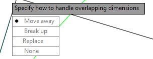
Another improvement to dimensioning functionality is the ability for AutoCAD to recognize when you are placing a dimension on top of an already existing dimension.  The software allows for 4 options when this occurs: move away, break up, replace and none.  
 
 
Let’s explore these options. The first picture shows the original dimension.  In the subsequent images, I am placing the same dimension on top of the existing dimension.  However, for each image I use one of the different options: move away, break up, replace or none.  


Image: Original dimension before a second dimension is placed on top


Image: Option 1 Move away
 

Image: Option 2 Break up

Image: Option 3 Replace

Image: Option 4 none
In short, the new updated dimension tool
• Predicts the type of object that is being dimensioned
• Changes the options for dimensioning depending on the object type
• Allows for options when placing a dimension on top of an already existing dimension


For more information on training and consulting for the various products Ideate services, visit our website at
www.ideateinc.com


Kate Ming

Ideate AEC Application Specialist

Kate is a California licensed civil engineer with a BS in Civil and Environmental Engineering from UC Berkeley. Prior to Ideate, she worked at a multinational company for four years doing general civil design on large infrastructure projects. She is versed in roadway, rail, utility design and site development. She also has experience with utility demand analysis and Low Impact Development plans. As a Civil 3D Autodesk Certified Professional Kate provides training and support for Civil 3D, AutoCAD, and InfraWorks.

April 14, 2015

AutoCAD 2016 New Dimension Tool

At Ideate, we always try our best to keep you abreast with the latest in the Autodesk world. So, here is a post dedicated to perhaps one of the biggest feature enhancements of AutoCAD 2016 – the new dimension tool. This will change your workflow forever, and for the better. Read on for a sneak preview of the tool. 
New Dimension Tool - Notice the Dimension Fly Out now
appears on the bottom row of the dimension panel.
As you can see from the above, the dimension fly out has been replaced with one command: dimension. This new tool is streamlined so that you don’t have to pick different commands for adding different types of dimensions. For example, you can add a linear, arc, circular, or angular dimension with one command, without having to quit and invoke the various dimension commands. As you invoke the dimension command, you will see options on your command line to switch the various options. The various dimension commands are now options of one dimension command.  
Dimension Commands
These options are smart because you don’t have to invoke them individually. AutoCAD automatically detects the object, and adds the appropriate annotation. Watch the short clip below and see how I don’t have to quit. All dimensions are added from the same command.


There is a layer control available from within the dimension panel. If you still want to use your dimension shortcuts, they will still work. The dimension fly out now appears in the bottom row of the dimension panel. You can see this in the first image in this post, where the text says "Linear" in the bottom left are.

This feature simplifies your workflow, and still allows for you to select your familiar dimension shortcuts. To check it out for yourself, go ahead and download AutoCAD 2016 trial today.

Gaurav Bagga
Ideate Infrastructure Solutions Application Specialist

Gaurav is a well rounded Application Engineer and Project Manager for Infrastructure Solutions at Ideate based out of San Francisco. He has over 15 years experience in construction industry and has been helping numerous small, medium and ENR 500 firms maximize their CAD investment for the last ten years. Gaurav is an Autodesk Certified Instructor and Autodesk Civil 3D Implementation Certified Expert. He has taught at several conferences, CAD Camps and Autodesk University. He has taught AutoCAD, Civil 3D, Land Desktop and Map 3D to thousands of students and helps Ideate develop the Infrastructure Services curriculum and courses. With his extensive CAD technology background he helps Bay Area engineering and surveying firms analyze and improve their design and drawing production process thereby improving productivity and the bottom line. Follow Gaurav on Twitter: @BeGeez

Get it. Know it. Use it.