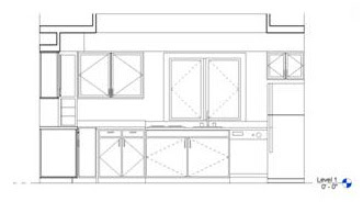
The first thing to do is generate your interior elevations. Figure 1 displays what will be displayed within the cropping boundary. After your Interior elevations have been created, access the Annotate tab; in the Detail panel select the drop-down arrow under the Region tool and choose the Masking Region tool. Figure 2:
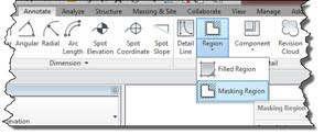
In the Modify|Create Masking Region Boundary tab select the
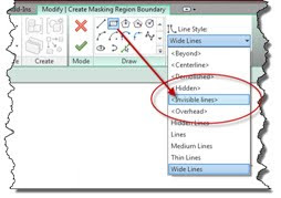
Next select your Line shape and choose Wide Lines (or your own desired Line Style) from the Line Style drop-down list. Draw the desired boundary around your room ensuring that you are outlining your soffits, casework, and anything else desired to form a closed boundary inside of your overall invisible line rectangle. This interior closed boundary “cuts” a hole in the middle of the mask displaying the model geometry beyond. Figure 4:
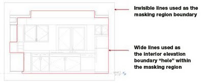
When finished creating the mask, press the Finish Edit Mode green check mark tool to finish the sketch. If you still see a rectangular box around your mask, in the View Control Bar at the bottom of the screen pick the Hide Crop Region tool to the left of the “sunglasses” tool. The Interior Elevation should be created and ready for you to add dimensions, text, tags, material tags, and keynotes. Figure 5:
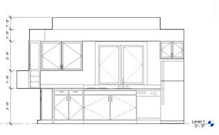
Have fun generating your interior elevations!
 Ron Palma
 AEC Solutions Application Specialist
Ron has 23+ years of experience in the AEC industry as a designer, lead project designer, trainer and CAD manager. His instructional background includes Autodesk Certified Instructor, trainer, support technician, educator at Portland Community College and Clackamas Community College, and a U.S. Army certified instructor. Follow Ron @RonPalmaAEC.
Get it. Know it. Use it.
